Routing issues accessing internal resources through VPN
1. Introduction
More and more the companies are allowing the employees to access the internal resources remotely. The good thing is that they are also concern about security. For remote access, the VPN still one of the most used solutions for small, medium and large companies. This scenario was based on a case that I worked when I was on the Platform team and it was about a problem while the user was trying to access an internal resource while connected through the VPN.
The user was traveling to participate on a congress and he was using the hotel’s network to connect to the VPN Server. The VPN connection successfully succeeds but the user was not able to access the file server located on the company’s network. Result: user was frustrated because he needs to have access to the file server right away.
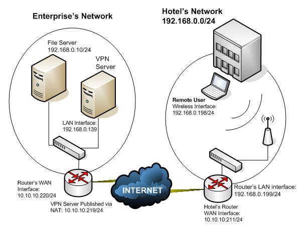
Figure 1 – Network Topology used in this case.
2. How the Routing Decision Works
On this case the problem was related to routing table, however I will get back to that on the next topic. Before explain the resolution for the case let’s review the essentials of routing decision. In this case the goal is to answer the question: how the host knows that needs to send a package to a local host or to the router?
When we add an IP address to the host the system will automatically create a routing table. If the default gateway address is not specified the system will create only routes to the local network. Let’s get an example of a host that has the IP address equals to 192.168.0.250. If the user only adds this IP on the TCP/IP properties and do not add the default gateway, the routing table will appear like that:
Network Destination |
Netmask |
Gateway |
Interface |
Metric |
127.0.0.0 |
255.0.0.0 |
127.0.0.1 |
127.0.0.1 |
1 |
192.168.0.0 |
255.255.255.0 |
192.168.0.250 |
192.168.0.250 |
20 |
192.168.0.250 |
255.255.255.255 |
127.0.0.1 |
127.0.0.1 |
20 |
192.168.0.255 |
255.255.255.255 |
192.168.0.250 |
192.168.0.250 |
20 |
224.0.0.0 |
240.0.0.0 |
192.168.0.250 |
192.168.0.250 |
20 |
255.255.255.255 |
255.255.255.255 |
192.168.0.250 |
192.168.0.250 |
1 |
Here the description of the main IP’s that is in use on this table:
· 127.0.0.0/8 – This is reserved for loopback purpose. As you can see, this network is using the interface 127.0.0.1 which is the host itself. This address is defined on RFC 3330.
· 192.168.0.0/24 – This is the route for the network that the host belongs to. The interface that will be used to handle this package is the host’s local interface (192.168.0.250).
· 192.168.0.250 – This is the route for the points to the host itself (loopback address).
· 192.168.0.255 – This is the route for the local broadcast. The interface that will be used for that is the host’s local interface (192.168.0.250).
· 224.0.0.0 – This is a reserved block for multicast purpose. The interface that will be used for that is the host’s local interface (192.168.0.250). This address is also defined on RFC 3330.
· 255.255.255.255 – Used for broadcasting purpose.
On the routing table above you could see that there is no default route and this is because we don’t have a default gateway specified on the host. This will limit the communication from this host to only other hosts that are on the local segment. For example: if this host uses the command ping 10.10.10.1 the result will be the error Destination Unreachable. Since we don’t have route for that and we don’t have no one to ask for help we can’t deliver the package.
Besides that, also notice that the last column on this table defines the Metric. The Metric is used to prioritize the path that the host will use to send the package. In case we have two entries on the routing table for the same destination, the system will choose the route with lower metric.
Now let’s see what will be different if we just add the default gateway to the TCP/IP stack of this host:
Network Destination |
Netmask |
Gateway |
Interface |
Metric |
0.0.0.0 |
0.0.0.0 |
192.168.0.3 |
192.168.0.250 |
20 |
127.0.0.0 |
255.0.0.0 |
127.0.0.1 |
127.0.0.1 |
1 |
192.168.0.0 |
255.255.255.0 |
192.168.0.250 |
192.168.0.250 |
20 |
192.168.0.250 |
255.255.255.255 |
127.0.0.1 |
127.0.0.1 |
20 |
192.168.0.255 |
255.255.255.255 |
192.168.0.250 |
192.168.0.250 |
20 |
224.0.0.0 |
240.0.0.0 |
192.168.0.250 |
192.168.0.250 |
20 |
255.255.255.255 |
255.255.255.255 |
192.168.0.250 |
192.168.0.250 |
1 |
The first route in this table is pretty much saying: If you don’t know to where to send this package, let this gateway (192.168.0.3) handle it. The 0.0.0.0 on the destination network means all networks and the 0.0.0.0 on the netmask means all netmasks.
2.1. ANDing
The process that the host will use to determine if the destination IP belongs to the local network or to a remote network is called ANDing . Let’s see one example:
The source host (192.168.1.200/24) is trying to ping the destination (192.168.2.200/24). At this point how the source host determines if the destination belongs to the local network or not?
Step 1 – Convert the decimal number in binary:
Decimal Notation |
Binary Notation |
Source |
|
192.168.1.200 |
11000000.10101000.00000001.11001000 |
255.255.255.0 |
11111111.11111111.11111111.00000000 |
Destination |
|
192.168.2.200 |
11000000.10101000.00000010.11001000 |
255.255.255.0 |
11111111.11111111.11111111.00000000 |
Step 2 – Use the Logical AND to find the result between the IP address and the netmask
0 |
AND |
0 |
= |
0 |
0 |
AND |
1 |
= |
0 |
1 |
AND |
0 |
= |
0 |
1 |
AND |
1 |
= |
1 |
This way we have the following result on the table:
Source IP |
Binary Notation |
Decimal Notation |
11000000.10101000.00000001.11001000 |
||
11111111.11111111.11111111.00000000 |
||
Source Network |
11000000.10101000.00000001.00000000 |
192.168.1.0 |
Destination IP |
Binary Notation |
Decimal Notation |
11000000.10101000.00000010.11001000 |
||
11111111.11111111.11111111.00000000 |
||
Destination Network |
11000000.10101000.00000010.00000000 |
192.168.2.0 |
As you can see source network and destination network doesn’t match, so the source host knows that the destination host is located on a remote network.
Now that we know how the routing decision works, let’s get back to the issue that this customer was facing.
3. Root Cause
When the remote client connected to the VPN the PPTP connection was receiving the IP 192.168.0.133/24 and the routing table was showing up like this:
Active Routes:
|
Network Destination |
Netmask |
Gateway |
Interface |
Metric |
|
0.0.0.0 |
0.0.0.0 |
192.168.0.133 |
192.168.0.133 |
1 |
|
0.0.0.0 |
0.0.0.0 |
192.168.0.199 |
192.168.0.198 |
21 |
|
10.10.10.219 |
255.255.255.255 |
192.168.0.199 |
192.168.0.198 |
20 |
|
127.0.0.0 |
255.0.0.0 |
127.0.0.1 |
127.0.0.1 |
1 |
|
192.168.0.0 |
255.255.255.0 |
192.168.0.198 |
192.168.0.198 |
20 |
|
192.168.0.133 |
255.255.255.255 |
127.0.0.1 |
127.0.0.1 |
50 |
|
192.168.0.198 |
255.255.255.255 |
127.0.0.1 |
127.0.0.1 |
20 |
|
192.168.0.255 |
255.255.255.255 |
192.168.0.133 |
192.168.0.133 |
50 |
|
192.168.0.255 |
255.255.255.255 |
192.168.0.198 |
192.168.0.198 |
20 |
|
224.0.0.0 |
240.0.0.0 |
192.168.0.198 |
192.168.0.198 |
20 |
|
224.0.0.0 |
240.0.0.0 |
192.168.0.133 |
192.168.0.133 |
1 |
|
255.255.255.255 |
255.255.255.255 |
192.168.0.198 |
192.168.0.198 |
1 |
|
Default Gateway: 192.168.0.133 |
|
| ||
The entry in red is the default gateway for the network 192.168.0.0/24, as you can see this route primary goes to the notebook’s wireless interface (192.168.0.198).
Now if you use the ANDing technique you will see that the host will determine that packages where the destination is the network 192.168.0.0/24 will be consider local (notice that the metric is lower) and therefore will not be send to the default gateway.
4. Solution
The packages to the network 192.168.0.0/24 were stuck locally since the metric is lower and therefore has more priority. The solution for that is to add another route entry changing the metric and forwarding the package to the default gateway (which is the IP received from the VPN Server), as show below:
ADD 192.168.0.0 MASK 255.255.255.0 192.168.0.133 METRIC 1
Now, the routing table will show like that:
Active Routes:
|
Network Destination |
Netmask |
Gateway |
Interface |
Metric |
|
0.0.0.0 |
0.0.0.0 |
192.168.0.133 |
192.168.0.133 |
1 |
|
0.0.0.0 |
0.0.0.0 |
192.168.0.199 |
192.168.0.198 |
21 |
|
10.10.10.219 |
255.255.255.255 |
192.168.0.199 |
192.168.0.198 |
20 |
|
127.0.0.0 |
255.0.0.0 |
127.0.0.1 |
127.0.0.1 |
1 |
|
192.168.0.0 |
255.255.255.0 |
192.168.0.133 |
192.168.0.133 |
1 |
|
192.168.0.133 |
255.255.255.255 |
127.0.0.1 |
127.0.0.1 |
50 |
|
192.168.0.198 |
255.255.255.255 |
127.0.0.1 |
127.0.0.1 |
20 |
|
192.168.0.255 |
255.255.255.255 |
192.168.0.133 |
192.168.0.133 |
50 |
|
192.168.0.255 |
255.255.255.255 |
192.168.0.198 |
192.168.0.198 |
20 |
|
224.0.0.0 |
240.0.0.0 |
192.168.0.198 |
192.168.0.198 |
20 |
|
224.0.0.0 |
240.0.0.0 |
192.168.0.133 |
192.168.0.133 |
1 |
|
255.255.255.255 |
255.255.255.255 |
192.168.0.198 |
192.168.0.198 |
1 |
|
Default Gateway: 192.168.0.133 |
|
| ||
The host receives the IP 192.168.0.133 from the VPN Server and this route will force the host to use this interface primarily to send packages to the 192.168.0.0/24 network.
But, the solution couldn’t be considered affordable if we didn’t have a automated way to implement it and fortunately we do. To do that we will use the CMAK (Connection Manager Administration Kit) to pass a TXT file as parameter that will contain the route add command as show below:
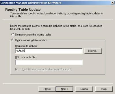
Figure 2 – CMAK window.
This TXT file will contain the following command line:
ADD 192.168.0.0 MASK 255.255.255.0 default METRIC default IF default
The syntax used on this command is different from the regular Route Add command. In this case the keyword DEFAULT before the metric means that we are assuming the IP received from the VPN Server. The keyword DEFAULT after the metric means the value that will be used for the metric; in this case it is 1. For more information on this command see the article Including Routing Table Updates on Microsoft TechNet.
5. Conclusion
This could be a really complex scenario if we didn’t know really how the routing process works. It is really important for any network administrator to be really sharp on this subject to mitigate possible issues and also to quickly identify possible problems.