Architecture Diagram: Blueprint for Enterprise Web Infrastructure
In the last two posts we have seen components for Microsoft WebStack and AppStack . In this post I will try put those together to build scalable web farm architecture that will act as our blueprint. Following functional diagram represent the logical view of web farm.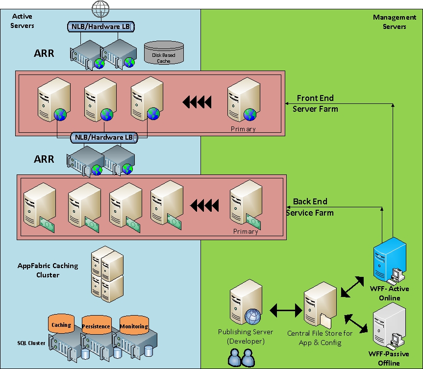
Above diagram represents architecture of two-tier data driven application as described below:
We have two ARR servers to distribute incoming requests to front end servers. These ARR server use memory based and disk based cache for static content. ARR serves are load balanced by either NLB or Hardware load balancer as purely Layer 4 (TCP) load balancer because ARR is acting as Application level load balancer.
Front End servers are stateless server deployed in DMZ responsible for serving ASP.Net pages to clients. These servers don’t store any information locally. Session state and any use specific information is stored on AppFabric Caching cluster with local cache enabled.
We have another set of ARR servers to load balance backend service.
Backend servers are responsible for WCF/WF services. These servers are running AppFabric Hosting services, Monitoring and caching client.
We have AppFabric caching cluster for distributed memory cache with fault tolerance enabled to optimize performance and resiliency.
We have SQL Cluster hosting multiple databases needed by Application/ASP.Net and AppFabric. There are three important database for AppFabric:
- AppFabric Caching Database to store caching cluster information
- Persistence database to persist Workflows
- Monitoring Database to store AppFabric Monitoring information.
We have two WFF servers running in Active-Passive mode to manage the WebFarm.
- At any given time only Active WFF server is available on network for management and on passive node WebFarm service is disabled. These two servers are configured with Shared-config to synchronize configuration information among them so that in the event of failure of primary node Passive node can be bring online by starting the WebFarm Service.
- WFF takes care of adding and removing servers in Web farm. It is configured with two Web farms where servers are grouped together depending upon their role either in FrontEnd or BackEnd webfarm.
- One server in each farm is marked as primary server that is not participating in receiving incoming traffic. These servers are used for synchronising application to other servers in farm. (Purely for non-technical (Admin) reasons primary server is not handling active client requests.)
Web applications can be provisioned/updated in two ways:
- First and preferred way is via self-service method. Delegations are enabled on application and users are designated as Site/Application administrator. They connect to Primary server remotely in each farm and upload new application. This is the preferred method because of self-service nature of it and no associated administration overhead. WFF will ensure that changes made to primary servers are replicated to other servers in web farm.
- Developers can publish a WebDeploy Package from publishing server to central file store. Administrators will create a Platform Provisioning task and as a part of it WebDeploy action will be executed on all servers and application will be provisioned.