Tip of the Day: VPN CSP’s, Schemas, and OMA-URI’s
Today’s Tip…
Yesterday’s tip outlined the methods that can be used to configure both networking policies and profiles (both VPN and Wi-Fi) on a Windows 10 device. Let’s recap in order of scalability…
The (simplified) UI – For base local configuration only. Not meant to expose confusing settings to novice users. Not intended as to scale to enterprise proportions.
PowerShell – Provides automated configuration for advanced features. Can be run on the local device manually or as a script. Can be scripted and run at scale targeting remote systems.
SCCM – The go to choice for exiting Enterprise infrastructures. SCCM allows administrators to deploy WMI (or OMA-URI) based policies to manage common configuration settings on all flavors of Windows devices.
Intune (MDM) - The challenger to our happy little on-premises ecosystem ;). The choice for Enterprises that want to expand their management infrastructures to support true mobility and BYOD. Intune leverages OMA specified platform-independent protocols providing a consistent management solution for devices of all persuasions; Windows, Android and iOS alike.
In today’s tip let’s take a closer look at concepts related to the latter. Specifically the client side configuration service provider (CSP), the CSP Schema, and setting specific URI’s (aka OMA-URI’s)
Configuration Service Provider (CSP)
As discussed in yesterday’s tip, the CSP is the client side agent that accepts and understands configuration statements pushed down in an XML-based format from an MDM server. It interprets the settings contained within a (SyncML) configuration profile, and applies them to the device accordingly in the form of registry settings, file settings, etc..
As with client side extensions, there is an individual CSP implemented for each of a platforms capabilities. See the following link for a complete list of Windows 10 CSP’s
Configuration Service Provider Reference
The CSP Schema
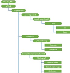
Individual CSP settings available within each CSP is represented by a schema, which when diagramed can be visualized as tree-format.
A root node can identify a specific vendor, for example “./Vendor/MSFT. A similar root node is used to specific schemas for other platforms, such as Android an iOS
An additional top level node is used to identify a specific CSP. For example, the Windows 10 VPN CSP is specified using the following syntax; ‘./Vendor/MSFT/VPNv2’.
Subsequent features and settings are targeted using by extending the syntax even further as illustrated by the following examples;
- ./Vendor/MSFT/VPNv2/profilename,
- ./Vendor/MSFT/VPNv2/profilename/AppTriggerList,
- ./Vendor/MSFT/VPNv2/profilename/TrafficFilterList,
and so on.
OMA-URI’s
You may have noticed the pattern coming together above when looking at the above examples. This is the common structure for OMA compliant configuration providers are referred to as ‘OMA-URI’s’. Here are a few more VPN related OMA-URI’s with brief descriptions.
./Vendor/MSFT/VPNv2
The root node for the VPNv2 configuration service provider.
VPNv2/ProfileName
Unique alpha numeric identifier for the profile. The profile name must not include a forward slash (/).
Supported operations include Get, Add, Replace, and Delete.
VPNv2/ProfileName/AppTriggerList
Optional node. List of applications set to trigger the VPN. If any of these apps are launched and the VPN profile is currently the active profile, this VPN profile will be triggered to connect.
VPNv2/ProfileName/RouteList/
Optional node. List of routes to be added to the routing table for the VPN interface. This is required for split tunneling case where the VPN server site has more subnets that the default subnet based on the IP assigned to the interface.
Every computer that runs TCP/IP makes routing decisions. These decisions are controlled by the IP routing table. Adding values under this node updates the routing table with routes for the VPN interface post connection. The values under this node represent the destination prefix of IP routes. A destination prefix consists of an IP address prefix and a prefix length.
Adding a route here allows the networking stack to identify the traffic that needs to go over the VPN interface for split tunnel VPN. Some VPN servers can configure this during connect negotiation and do not need this information in the VPN Profile. Please check with your VPN server administrator to determine whether you need this information in the VPN profile.
VPNv2/ProfileName/TrafficFilterList
An optional node that specifies a list of rules. Only traffic that matches these rules can be sent via the VPN Interface.
Note Once a TrafficFilterList is added, all traffic are blocked other than the ones matching the rules.
When adding multiple rules, each rule operates based on an OR with the other rules. Within each rule, each property operates based on an AND with each other.
VPNv2/ProfileName/NativeProfile
Nodes under NativeProfile are required when using a Windows Inbox VPN Protocol (Ikev2, PPTP, L2TP).
VPNv2/ProfileName/NativeProfile/Servers
Required for native profiles. Public or routable IP address or DNS name for the VPN gateway. It can point to the external IP of a gateway or a virtual IP for a server farm. Examples, 208.147.66.130 or vpn.contoso.com.
Value type is chr. Supported operations include Get, Add, Replace, and Delete.
VPNv2/ProfileName/NativeProfile/RoutingPolicyType
Optional for native profiles. Type of routing policy. This value can be one of the following:
- SplitTunnel - Traffic can go over any interface as determined by the networking stack.
- ForceTunnel - All IP traffic must go over the VPN interface.
More Information on CSPs
For additional information on configuration service providers (CSP), including the complete schema, OMA-URI’s, example definition file and configuration command syntax see the following links:

