Public IP Address Requirements within a Windows Azure Pack environment
Introduction
Hello everyone, this is Kenon Owens from the Windows Server and System Center CAT Team in Asia Pacific. I created this post as I have been working with customers recently who asked this question, and since they have, I am guessing more of you have the same or similar question.
Whether you are a Service Provider, Hoster, Telco, or a government agency or enterprise looking to treat your cloud infrastructure like a Service Provider, you will probably have tenants (customers) with a need to either get their VMs access to the internet (or their own private network), or want their VM publicly accessible from the internet. To do this, you will have to provide access for that VM to networks outside of the Windows Azure Pack (WAP) environment. Depending on the type of access your tenants require, this may mean you will have to give a VM a public IP address, or it may mean you will simply need an IP address for network access.
There are four common ways an organization will allow access from the Hyper-V Networked Virtualization environment within WAP out to the physical world. These are:
-
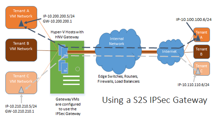
- Using a S2S IPSec Gateway
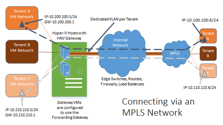
- Connecting via an MPLS Network (or equivalent)
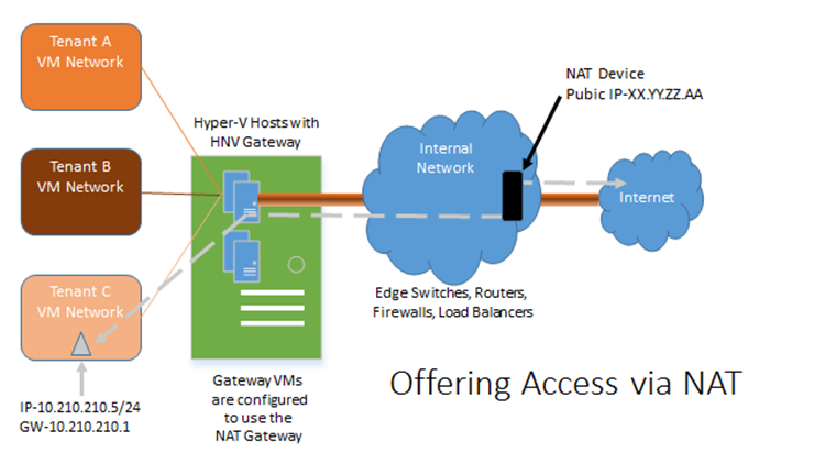
- Offering Access via NAT
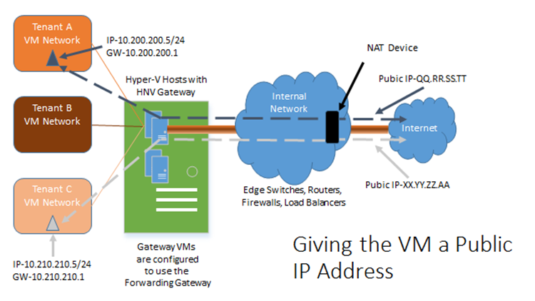
- Giving the VM a public IP address
- Remote Access VPN
For this blog, we will be focusing on the first 4 topics. For information on Remote Access VPN, please check out the following blog post by our Networking Team.
Before we go into this topic deeper, you may want to refresh how Hyper-V Network Virtualization works by reading the fantastic series posted by Nader Benmessaoud. To get the packets out from the Network Virtualization environment to the physical world, you will need to use an NVGRE Gateway to encapsulate and de-encapsulate the packets. Windows Server 2012 R2 provides a software NVGRE Gateway to do just this. There are also hardware versions that do this as well depending on what you need. I will be using the software NVGRE Gateway provided by Windows Server 2012 R2 in the examples below.
A more detailed description of each of these connection methods is described below:
Using the S2S IPSec Gateway
Using the S2S IPSec Gateway, you can extend a tenant’s network from their site to your WAP environment through an IPSec tunnel created on their premise and terminating at the Hyper-V Network Virtualization Gateway. This will allow encrypted traffic over the internet protecting your customer’s data while allowing them to access their network resources within your WAP environment as if it is part of their network. For the S2S IPSec Gateway to work, you will need to have a public IP available per NVGRE Gateway pair that the tenant can connect with to create the tunnel.
What this means is that Tenant A, Tenant B, and Tenant C have their own on premises networks (on the right hand side of the diagram above). Tenant A establishes an IPSec S2S connection to the NVGRE Gateway located at the hoster (on the left hand side of the diagram above). Once this connection is established, a machine within Tenant A’s on premises network (the one with 10.100.100.6 in the example above) can connect to the VM in the hoster (10.200.200.5 in the example above) as if it is on Tenant A’s own network even though the packets are traversing the Internet.
Connecting via an MPLS Network (or equivalent)
Another common way for a tenant to extend their network into your WAP environment is to use a connection method like MPLS to connect to your network. With this method, the packets are basically transferred over a dedicated circuit from the customer environment to your WAP environment. At one point in the path, the packets are most likely converted from the MPLS environment to an isolated VLAN per tenant to transfer packets in to and out of the customer’s WAP Virtual Network. You will not be able to set this method up by default through WAP, but, instead, will have to create automated scripts to modify the gateway to support forwarding to the NVGRE Gateway. You will also need to connect the NVGRE Gateway to the different VLANs used to support the VLAN per tenant. The NVGRE Gateway will use the forwarding method to access the physical wire. This type of connection may not require a public IP depending on your external networking setup as the network is an isolated connection.
What this means is that Tenant A, Tenant B, and Tenant C have their own on premises networks (on the right hand side of the diagram above). Tenant A has established an MPLS connection to the hoster’s network. Tenant A can now establish a connection to the NVGRE Gateway located at the hoster (on the left hand side of the diagram above). Once this connection is established, a machine within Tenant A’s on premises network (the one with 10.100.100.6 in the example above) can connect to the VM in the hoster (10.200.200.5 in the example above) as if it is on Tenant A’s own network.
Offering Access via NAT
This method is very similar to how one would connect their machines at home through a cable modem. The VMs can get out, and can initiate connections, but they are not physically addressable from the internet. This method is common for development and test VMs as well as VMs that will only need external access for downloading things like patches. With System Center 2012 R2 Virtual Machine Manager as the backend Fabric Manager, you will need to setup NAT in the environment per VM Network. For this type of connection, you will need one public IP address per VM Network.
What this means is that Tenant A, Tenant B, and Tenant C have their own virtual networks located at the hoster on the left hand side of the diagram above). Tenant C’s VMs can access the internet using NAT in the same way someone would use a cablemodem to access the internet at home, or use WiFi to access the internet at a coffee shop.
Giving the VM a public IP address
For this type of connection, your tenants’ VMs will be on the internet and accessible by IP directly out of the WAP networking environment. This configuration will be using the forwarding aspect of the NVGRE Gateway, and most likely the public IP won’t be directly passed through into the WAP environment, but instead there will be network translation done at a device further upstream. This method will require one (or more) IPs per VM.
What this means is that Tenant A, Tenant B, and Tenant C have their own virtual networks located at the hoster on the left hand side of the diagram above). Tenant C’s VMs can have a publicly accessible IP address (XX.YY.ZZ.AA in the example above) that get routed into the actual VM running on Tenant C’s isolated VM network.
So, how many Public IP Addresses do I Need?
I was working with a customer on their networking design about this, and figuring out what public IP requirements are needed was an interesting exercise. I put the following together, and wanted to share it out to help lessen the time it will take you to architect a similar solution.
The objective of this table is to figure out how many Public IP addresses you are going to need on the outside of the WAP environment to support ~8000 VMs. With that many VMs, you may need a lot of public facing IP addresses.
Connection Type |
%Customers using this method |
Gateway Configuration |
# Public IP addresses for NVGRE Gateway Pair |
# Public IP for VM in question |
# of vm networks per NVGRE Gateway Pair |
# of Public IP for 8000 VM Configuration |
IPSec S2S Gateway |
45 |
IPSec S2S |
1 per NVGRE Gateway Pair |
0 |
100 |
8 |
MPLS** Connection |
30 |
Forwarding |
0 |
0 |
1 |
0 |
Traditional NAT |
15 |
NAT |
1 per VM Network |
0 |
>200 |
240 |
Public IP |
10 |
Forwarding |
0 |
1 per VM |
>200 |
800 |
* For this table we are assuming 5 VMs per VM Network
** For MPLS Connections as stated above, depending on your network, you may require multiple public IP addresses if your physical MPLS connections require this.
For the NVGRE Gateway, you will also need a number of Private IPs to create the clustered NVGRE Gateway Pair. You will need to have this gateway pair cluster be on the physical network, which means you will need IP addresses in your private Range for the physical network they are connected to. This will require at least 3 IP addresses for the Cluster. One IP for each Node, and one IP for the Cluster itself.
For the Number of Public IPs needed, these are public IP addresses that can be addressable from outside the hoster network.
Here are the formulas I used for determining the # of Public IP for this proposed 8000 VM Configuration:
- IPSec S2S Gateway
- (#VMs) * (%age of customers) / (5 VMs/VM Network) / (200 VM Networks/NVGRE Gateway pair) * (1 Public IP/NVGRE Gateway Pair)
- 8000 * .45 / 5 / 100 * 1
- MPLS Connection
- 0 because number of Public IPs = 0
- Traditional NAT
- (#VMs) * (%age of customers) / (5 VMs/VM Network) * (1 Public IP/ VM Network)
- 8000 * .15 / 5 * 1
- Public IP
- (#VMs) * (%age of customers) * (1 Public IP/VM)
- 8000 * .10 * 1
Now, your mileage may vary. It really depends on the split of the types of connections you will support. Also, if you add in a scenario where one VM may have multiple connection types (say a S2S IPSec Gateway on one virtual network adapter connecting to the tenant network over IPSec, and NAT for internet access (to download software patches or such)), then the tenant may need more Public IP addresses.
Now, to support this volume of public facing IP addresses, you will probably have to use a mix of IPv4 and IPv6 addresses, but that is a topic for a different discussion.
I hope this helps to clarify what types of networks your tenants may use in a WAP environment and how many IP addresses you will have to set aside to support your requirements.


