Configuring the VMM Fabric For Windows Azure Pack
This is the second article in a series of blog posts that will guide you through a simple implementation of a self-service private cloud interface using Windows Azure Pack. There are many layers of the application, and the underlying infrastructure, when implementing this solution. As we progress through the series we will lay out a scenario, a set of requirements, and provide guidance on how to implement each of the numerous prerequisites, with the ultimate goal of a self-service portal that your team can use to create and manage their own virtual machines.
This article goes over the configuration of the VMM fabric in preparation for the installation of Windows Azure Pack. The roadmap for this and subsequent articles is:
- Requirements, Architecture, and Prerequisites
- Configuring the VMM Fabric For Windows Azure Pack (This Article)
- Configuring Service Provider Foundation
- Windows Azure Pack Installation
- Windows Azure Pack Configuration
- Windows Azure Pack Customization
- Windows Azure Pack Usage
Creating a Cloud
Just like a real cloud, made up of many drops of water, a computing cloud is made up of multiple virtual resources, deployed on an infrastructure composed of several physical hardware components. The collection of resources, physical and virtual, is the fabric on which a cloud service is built. Setting up the fabric on a VMM cluster can be a complex undertaking. For simplicity, only the required components for our scenario will be described. Additional features like virtualization, and port classification will be discussed later in this entry after the configuration.
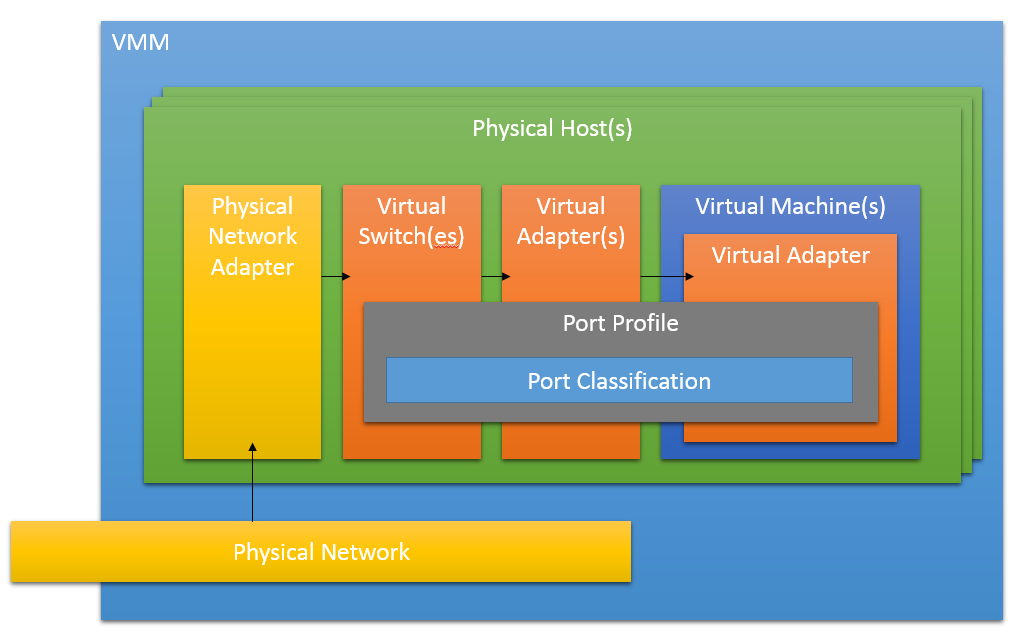
A Fabric in its simplest terms, is a configuration set that allows Hyper-V nodes and their guest VMs communicate to each other, and the rest of the network. The fabric creates virtual network components, with a standardized configuration, on physical hardware on each of the Hyper-V nodes in the cluster. Once this underlying configuration is created, deployed VMs are able to each communicate with each other as if they are connected physically to the same network. Below is a list of the individual components in VMM, each linked to a descriptive TechNet article.
- Host Group – Logical group of Hyper-V resources
- Logical Network – A virtual network, from the physical network, to which virtual network components will be connected
- Port Profile – A common set of configurations for virtual switches and virtual adapters
- Logical Switch – A virtual switch connecting one or more virtual adapters to a logical network
- Port Classification – A common set of configurations that can be used by multiple port profiles.
- VM Network – A virtual network through which VMs are able to communicate with each other built on top of a Logical Network
- Cloud – A common set of configurations that encapsulate the fabric, and physical resources. Allows tenants to deploy VMs while adhering to the limitations of the cloud.
Below, we are going to go over setting up each of these components while staying within the requirements of our scenario from the first entry in this series.
Creating Host Groups
A Host Group in VMM is a logical grouping of Hyper-V servers that can be reserved for specific purposes, or identified as a whole for advanced operations via PowerShell. In our scenario, we are going to create two host groups, setting aside the Hyper-V node running VMM as the Admin group, and providing the rest to our cloud. This ensures that we have a space to set up administrative VMs for services like Windows Azure Pack, or an SQL instance for tenants. To do this, we’ll create two groups in the VMM fabric with the following steps:
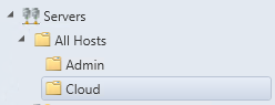
Click Fabric -> right click All Hosts -> create host group -> Admin
Click Fabric -> right click All Hosts -> create host group -> Cloud
When we created our VMM cluster, we put all of our hosts into the All Hosts group. To move the hosts into the appropriate group, do the following for each host:
Click Fabric -> select All Hosts -> right click host1.domain.local -> move to host group
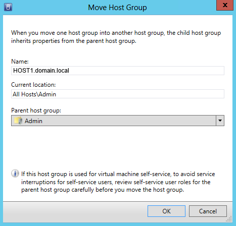
Change Parent host group to Admin, click OK.
Repeat for remaining nodes in the cluster, moving them to the Cloud host group.
Creating a logical network
Our next step in creating our fabric for our cloud is to create a logical network. The logical network in VMM is a virtual network built on a physical network. A logical network can be simple or very complex, setting up IP address pools, DNS, VLANs, and IP Subnets for example. Our Scenario uses a DHCP server, and an existing IP address configuration, with DNS integration provided by Active Directory. This enables us to use the default settings in most cases as we create the fabric in subsequent steps.
To create the Logical networking perform the following steps:
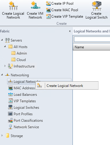
Click Fabric -> expand Networking -> select Logical Networks -> Create Logical Network from ribbon or right-click Logical Networks to start wizard.
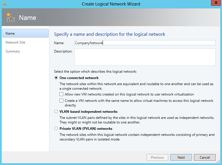
The start page for the Logical Network wizard provides many alternatives for how our network will ultimately be configured. In our scenario we are going to use a single connected network, without using virtualization. This means that each VM that we create should be able to connect directly to our company’s network, and should be reachable from anywhere on that network. Alternative solutions, include network virtualization, will be reviewed in the in the Alternative Options sections later in this blog entry.
To begin enter a name for the new network, e.g.: “CompanyNetwork”. Select One connected network, and click Next.
Select All Hosts from the host groups, click insert row, enter the IP subnet, e.g.: 10.0.0.0/24, click finish, and a job will be created to create the network. Here we’re using the IP subnet values provided by the underlying physical network provided for the scenario.
Port Profiles
In VMM, port profiles are containers for standard configuration and capabilities for network adapters and switches. A port profile enables VMM to setup a consistent set of capabilities for all hosts in a cluster, rather than configuring each individually.
For our scenario, we require an Uplink Port Profile. To start, perform the following:
Click Fabric -> expand Networking -> select Port Profiles -> Create Hyper-V Port Profile from create on ribbon or right-click Port Profiles to start wizard
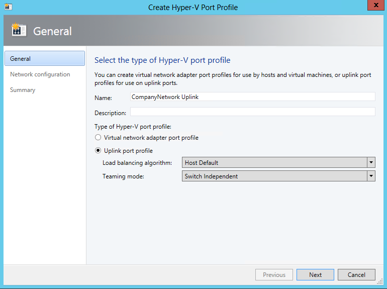
Enter a name for our uplink port profile, select Uplink port profile, leaving default options, and click Next.
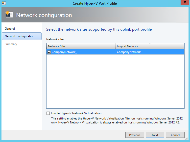
Select our previously created network site CompanyNetwork_0 created automatically when we created on our logical network CompanyNetwork, and hit next.
Click Finish to complete the wizard, and the new Uplink Port Profile will be available from the Port Profiles networking section.
Logical Switches
In VMM, a logical switch is a virtual switch configured and placed on each Hyper-V host. This group of switches allow the virtual network adapters that connect to it to appear they are connecting to the same device in the fabric. To create our logical switch perform the following:
Click Fabric -> expand Networking -> select Logical Switches -> Create Logical Switch from ribbon, or right-click Logical Switches to start wizard
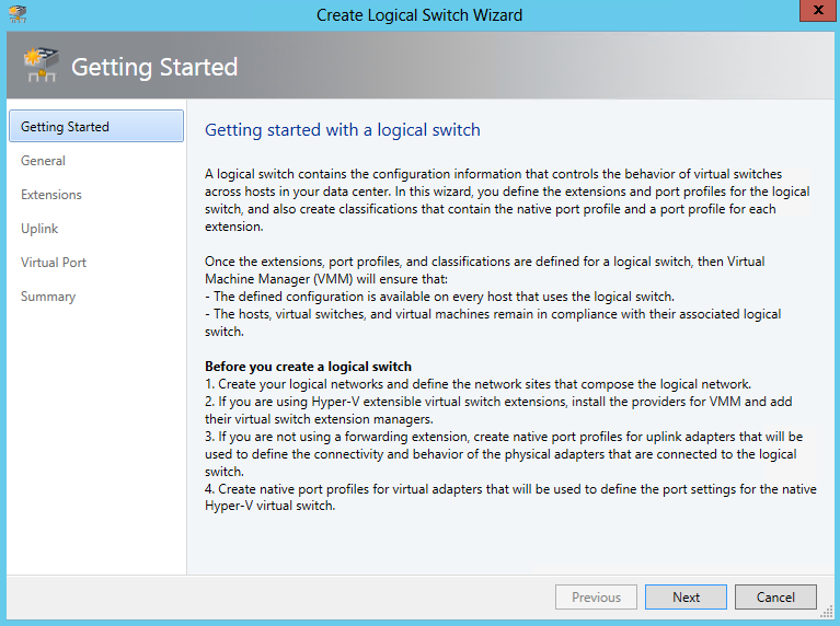
The getting started page describes the basic functionality of the logical switch, as well as the prerequisites, which we have luckily covered in the previous sections. Click Next to continue.
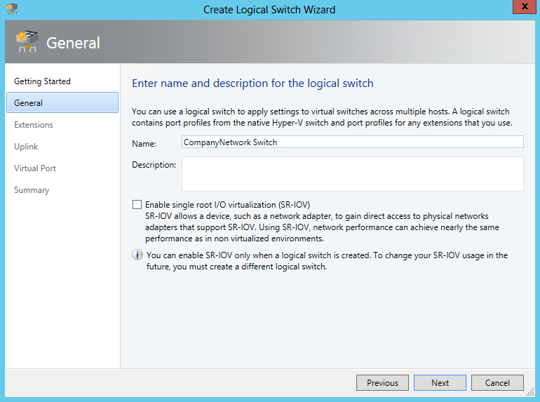
Enter the switch name, “CompanyNetwork Switch” and click Next.
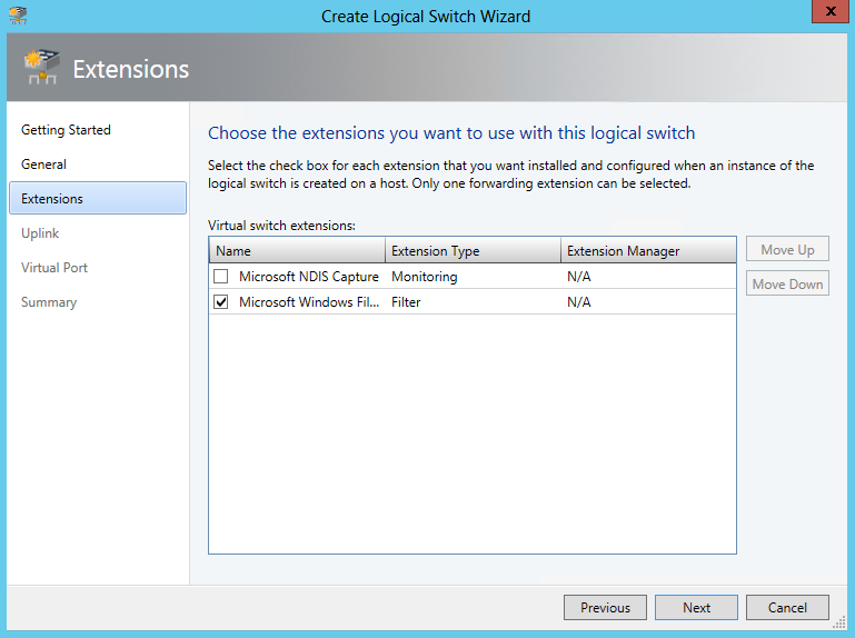
Leave default extensions selected, and click Next.
On the uplink profiles page, click Add.
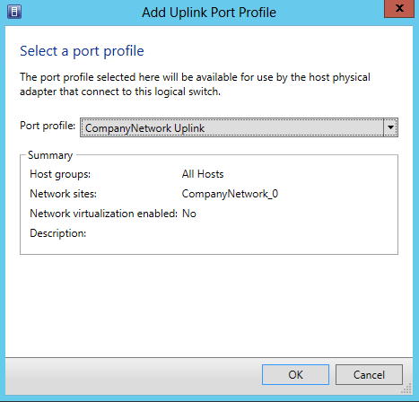
Select our port profile CompanyNetwork Uplink and click OK.
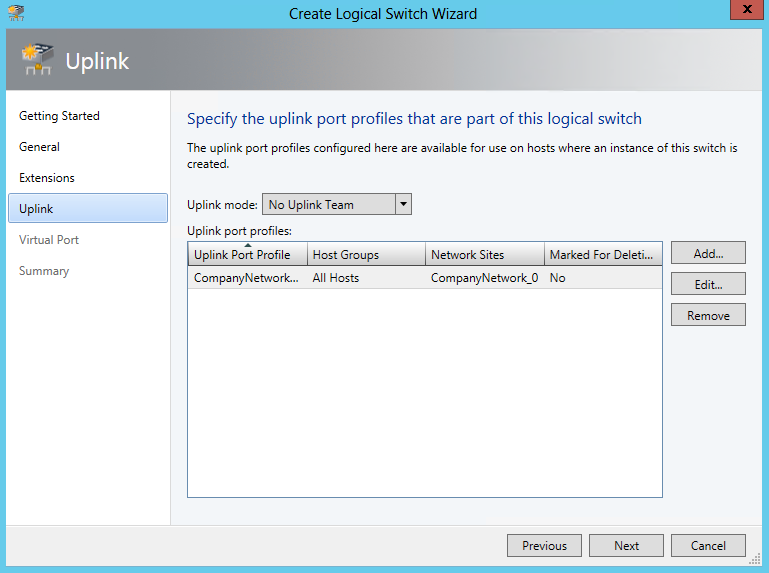
Once uplink port profile is added click Next.
On the port classifications page, click Add, and click Browse
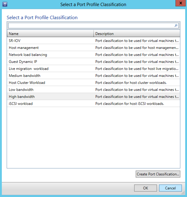
Select High bandwidth, and click Ok
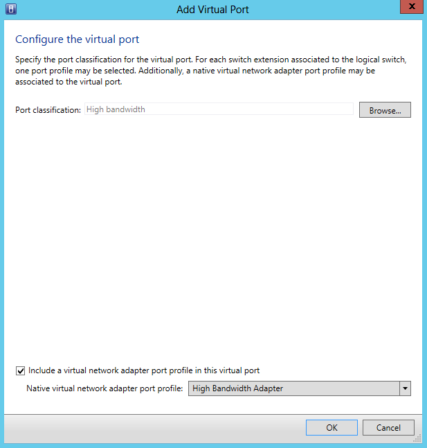
Select Include a virtual network adapter port profile, and select the High Bandwidth Adapter and click Ok
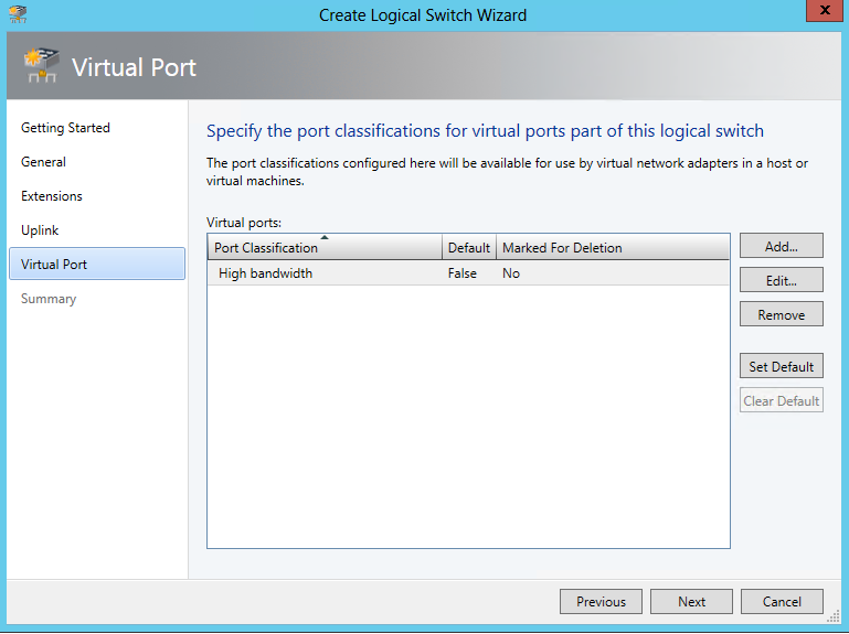
Once the port classification has been added click next. Alternative options for port classifications can be found in the Alternative Options section
Click finish on the summary page, and the wizard will close, and create a job to create the new logical switch
Create VM Network
Now that the virtual network components have been created, we need to create a VM network. A VM Network is a virtual network created on top of the Logical Network in our fabric. As mentioned before, VMM provides much functionality that our scenario does not require, such as creating multiple virtual networks with different capabilities over the logical network. In our example we are only using a single VM Network however. To begin, perform the following:
Click VMs and Services -> Create VM Network from ribbon, or right-click VM Networks to start wizard.
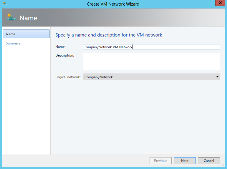
Enter a descriptive Name, select the created logical network “CompanyNetwork”, and click next. Click finish to finish the wizard, and a job will be created to create the new VM network.
Configuring Hyper-V nodes with new fabric
Once all the networking components are configured in VMM, it is time to configure the virtual networking components to the physical networking components on each of the Hyper-V nodes.
Note: Performing these steps can interrupt networking activity on the physical machines, and physical access to the machines may be required to repair network connectivity if any of the VMM jobs fail.
To begin, perform the following:
Click Fabric -> All Hosts -> right click host1.domain.local -> Properties -> Virtual Switches
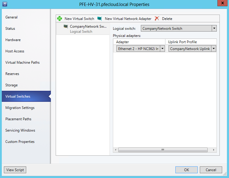
Click New Virtual switch -> New Logical Switch and to select the previously created Logical Switch and Uplink Port Profile.
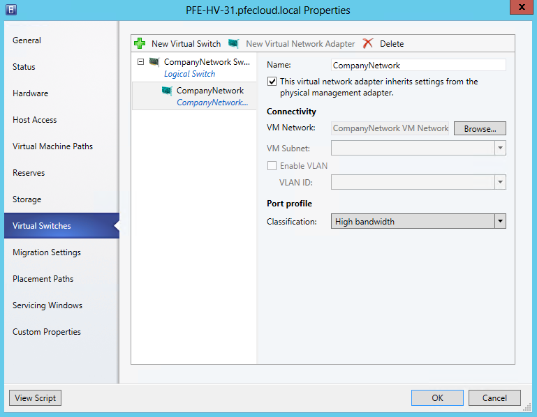
Click New Virtual Network Adapter, enter CompanyNetwork for the adapter name, and select the physical inheritance option. Select the port profile “High bandwidth” for our logical switch and click OK. The inheritance option will reuse the existing network configuration from the physical adapter on the new virtual adapter. You will get a warning that you may temporarily lose network connectivity, which you will need to confirm. A Job will be created to apply the new changes to the node. If the job is unsuccessful, physical access to the machines may be required to reconfigure the physical network components.
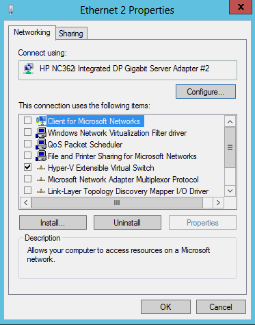
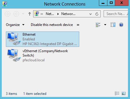
Once the job has completed some networking changes will have been made on the physical node. The original network adapter device is now configured solely as a Hyper-V Extensible Virtual Switch, and a new vEthernet adapter has been created. This new device is configured with the configuration settings (e.g. protocols, IP and DNS values) from the original physical adapter.
This process will need to be repeated for all Hyper-V servers in the VMM cluster.
Creating the Cloud
Now that the virtual networking components have been configured and linked to the physical components in the cluster, the final step is to establish a cloud on the new fabric. The cloud allows you to create a logical grouping of all of our new components, as well as setup resource limitations if needed. In our previous steps, we created only what was necessary for our single cloud, so many of the options for configuring our new cloud will seem straightforward. To begin, perform the following:
Click VMs and Services -> Create Cloud from ribbon, or by right clicking clouds to start the wizard
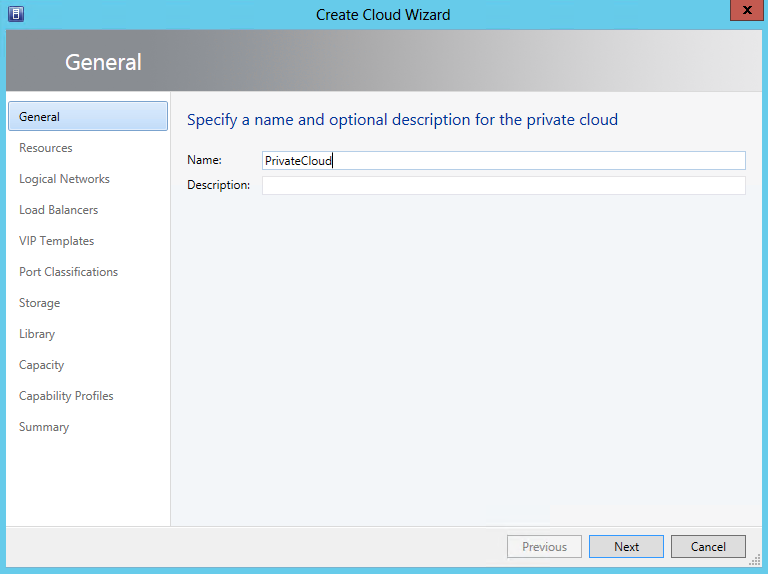
Start by selecting a name for the new cloud. In our example, we are creating a single private cloud so we set the name to something simple, PrivateCloud. Click Next.
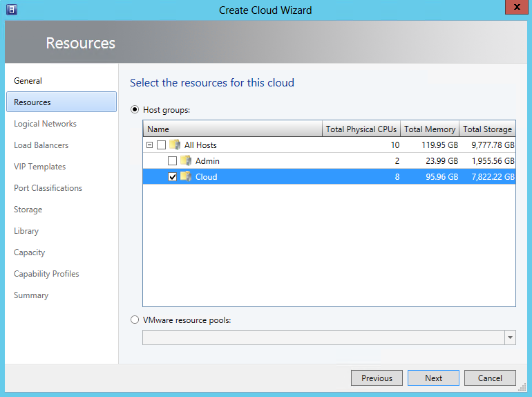
For our purposes, we only want to select the Host Group that we set aside for the cloud in the previous steps. This allows us to keep a set of physical machines (the VMM node Hyper-V instance) for our own purposes, without creating utilization on the cloud Host Group. We will use the Admin Host Group later to create the WAP portal, as well as additional WAP services, like SQL Server. Select Cloud and Click Next.
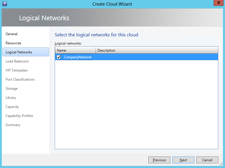
Select the logical network that we configured earlier, CompanyNetwork, and click Next.
Continue on the wizard by clicking Next on the LoadBalancer configuration, and VIP Templates pages, until you get to the Port Classifications.
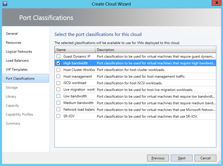
Select the High Bandwidth port classification we used earlier, and click Next
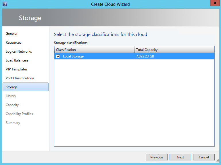
Select Local Storage, and click Next.
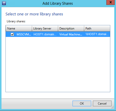
Click Add, and select the MSSCVMMLibrary value configured during the original VMM installation, and click OK and click Next
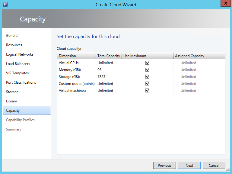
Setup any limitations on resources that you require. In our scenario, the host group that we set up is set aside for only the cloud, so we are leaving most settings as Unlimited, though in actuality the resources of the underlying Hyper-V will impose limits. Click Next.
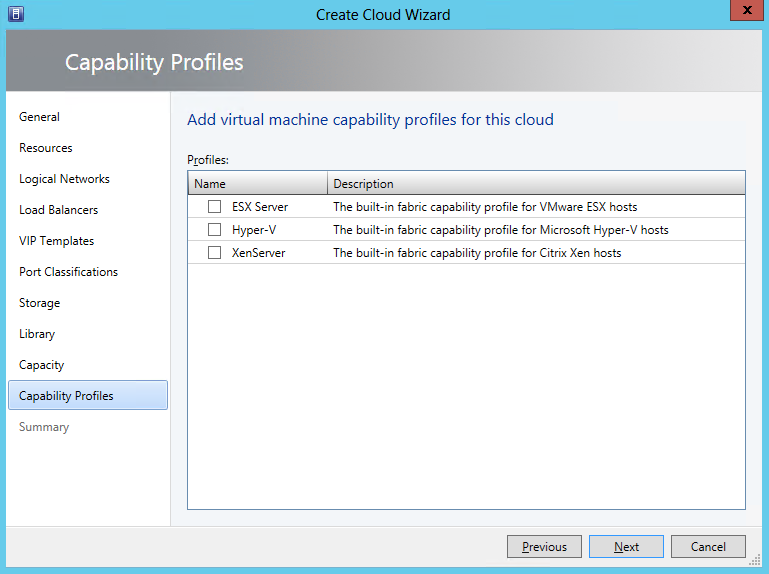
Leave all capabilities checkboxes unchecked. Selecting capabilities at this point will create issues when WAP attempts to use the cloud later. Click Next and then click Finish. Once complete a Job will be created, and the cloud will be configured.
Alternative Options
The following sections contain alternative options for our simple scenario. The ability to customize the fabric in VMM will allow you to cater the implementation based on your own requirements.
Network virtualization
In System Center 2012 SP1 + R2, Network Virtualization was developed. The idea behind virtualization is it allows you to encapsulate an entire virtual network, allowing for multi-tenant configuration, inside a VM/Logical/Physical network. Additional details around network virtualization can be found in the following article
Hyper-V Network Virtualization technical details
Port classifications
In a complex VMM architecture, there may be multiple physical connections, logical networks, and virtual hardware. Each of these networks can have multiple roles, like high-availability, live migration, administrative, tenant, etc. Each of these can be set up with different port classifications and associated port profiles, enabling you to shape the traffic between physical and virtual hosts. More details on how to configure Ports and Switches can be found in the following article
Configuring Ports and Switches for VM Networks in VMM
Finishing Up and Next Steps
This concludes the configuration of the VMM fabric, with a functioning VMM cluster prepared for the next steps in deploying Windows Azure Pack. Our next steps will be to add the Service Provider Foundation, a necessary prerequisite for WAP, and other preparations for installation.
- Requirements, Architecture, and Prerequisites
- Configuring the VMM fabric
- Configuring Service Provider Foundation (the next installment)
- Windows Azure Pack installation
- Windows Azure Pack configuration
- Windows Azure Pack customization
- Windows Azure Pack Usage