Using Color Rules to Show Direction
By Jin Feng
Differentiating client requests and server responses can provide a clear-cut view and make it easier to understand what’s going on within a trace. Normally, with a flat trace this can be hard to determine and distinguish one packet from another. However with Network Monitor Color rules, it enables us to highlight frames matching a rule in a specified color and using a specified text style, which we can use to do this job very well. For more information on creating color rules, you can reference this blog. Let’s drill down to see how it works.
Finding the Right Direction Filter
The most import thing is to identify the correct filter expressions and then use that to apply any color rule. We can find “Direction” information in different protocols at different protocol layers, but substantially this information comes from the Network Layer. We have already defined a property, “NetworkDirection”, in Network Layer protocols like IPv4, IPv6 and IPX. For example in IPv4 it is defined as:
[ Property.NetworkDirection = (SourceAddress > DestinationAddress) ? 1 : (SourceAddress == DestinationAddress) ? 0 : 2 ]
Note: Properties are defined in the parser files and are set as a frame is parsed. You can consider them as meta data and they have multiple uses. See this Wiki Reference which describes some useful properties and provides a more complete definition. The example code can be found in the ipv4.npl file (installed by default in C:\ProgramData\Microsoft\Network Monitor 3\NPL\NetworkMonitor Parsers\Base\).
So a value of 1 represents one direction and 2 represents the reverse one. The actual direction is arbitrary based on which address is the larger one numerically. Thus for most traces we can define different color rules with the following two filter expressions to show direction:
- Property.NetworkDirection == 1
- Property.NetworkDirection == 2
Identifying Local Traffic
You might ask how about “Property.NetworkDirection == 0”, is that possible? The answer is yes, if you can configure your computer to capture traffic from itself. In this case the above filter expressions won’t work anymore, and we need more information from Transport Layer, for example TCP. There is already a property “TCPDirection” defined in TCP.npl:
 [
    Property.TcpDirection = (Property.SourceNetworkAddress>Property.DestinationNetworkAddress)?1
                        :(Property.SourceNetworkAddress<Property.DestinationNetworkAddress)?-1
                        :(Property.SourcePort>Property.DestinationPort)?1
                    :(Property.SourcePort<Property.DestinationPort)?-1:0
]
Using the following two filter expressions will show direction correctly even when the src/dst network addresses are the same.
- Property.NetworkDirection == 1 || ( Property.NetworkDirection == 0 && Property.TcpDirection == 1 )
- Property.NetworkDirection == 2 || ( Property.NetworkDirection == 0 && Property.TcpDirection == -1 )
Note that this works for TCP traffic only. But as we now have a property for UDPDirection, the same color filters could be created for UDP traffic.
Broadcast Traffic
Another possibility is broadcast traffic. The “direction” is defined differently in this case. We can identify a filter expression for this traffic and apply a specific color filter for these ahead of previous direction filters so that broadcasts have a higher priority. Keep in mind that one frame can only have one color rule applied. Color rules are applied in order; once a color rule matches, the following ones will be ignored. The filter expression for broadcast would be:
 Ethernet.DestinationAddress == FF-FF-FF-FF-FF-FF ||
Property.WiFiDestination == FF-FF-FF-FF-FF-FF ||
IPv4.DestinationAddress == 255.255.255.255 ||
IPX.DestAddress == 0xFFFFFFFF
Color Rules from CodePlex
Colors rules, along with standard filters and parsers, are included as part of each CodePlex parser release. We’ve included this filter with the latest parsers from CodePlex. You can enable the Network Direction color rule from the new Color Rules button in Network Monitor 3.4.
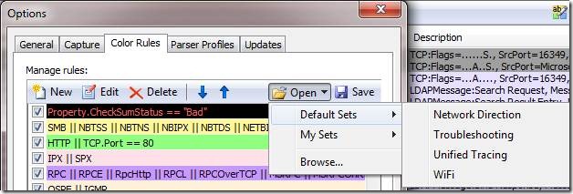
When the Color Rules window opens, select the Open button drop down and you’ll find Network Direction in the Default Sets folder.
These rules will be added to the top or bottom of the list depending on the checkbox setting for appending new rules.
Color Filters for Clarity
So here's an example of broadcast traffic represented with a pinkish background, and traffic in one direction represented by a yellow background. In this example, NetworkDirection==2 was not changed.
Using color filters to make traffic direction stand out is a great way to help understand traffic flow. Hopefully this is a feature you find useful and learn to incorporate into your troubleshooting techniques.


