Step-by-step for deploying a SDNv2 using VMM - Part 2
In the previous post, we talked about how to prepare a SDN lab environment. In this post, we will continue and deploy NC in the lab environment. Most of the steps here are same as the following official validation guides. However I will highlight some of the error-prone steps and provide step-by-step screenshots. Hopefully it could help you walk through the SDN deployment.
Add Hyper-V Hosts to the VMM
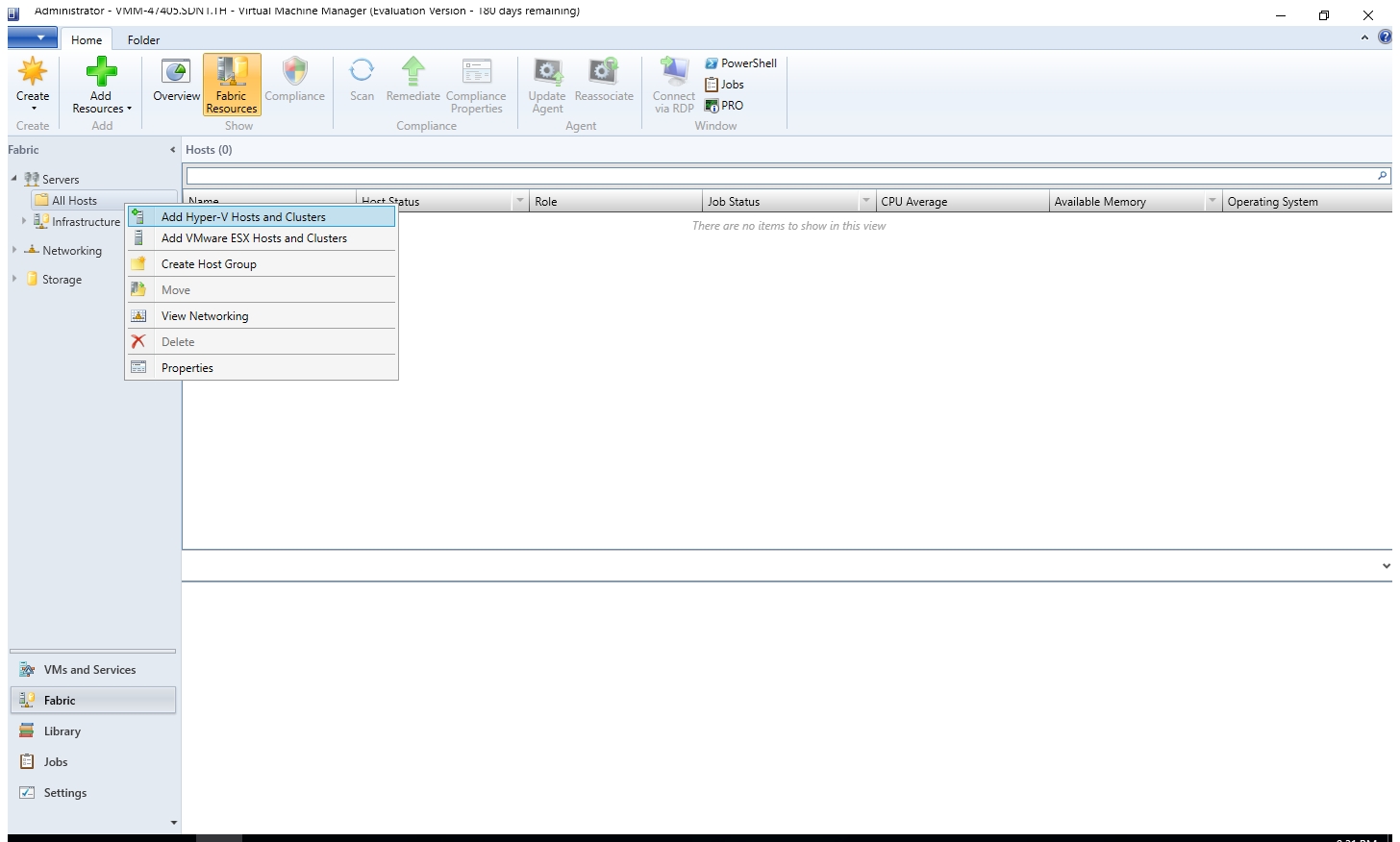
- Open VMM Console, click "Fabric" and expand the "Servers > All Hosts".
- Right click the "All Hosts" and select "Add Hyper-V Hosts and Clusters"

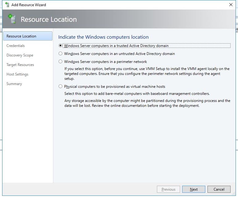
- Select "Windows Server computer in a trusted Active Directory domain".
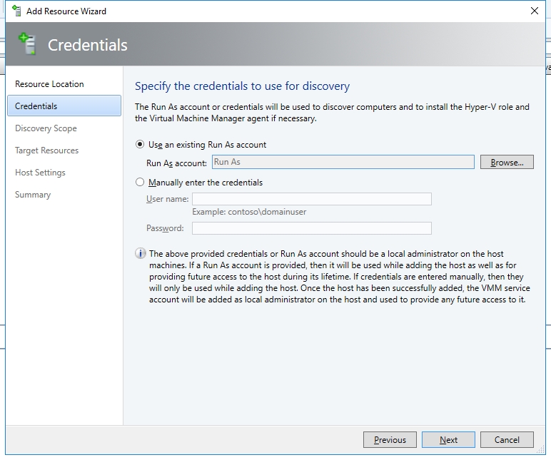
- In the next page, I created a Run As account, which is also a member domain admins group (That's not recommended for production environment.).
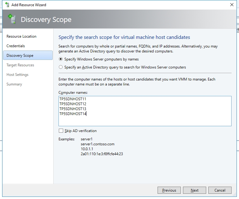
- Key in the computer name of the each Hyper-V hosts. Then click "Next".
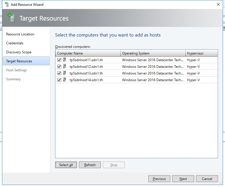
- Click the button "Select All", then click "Next".
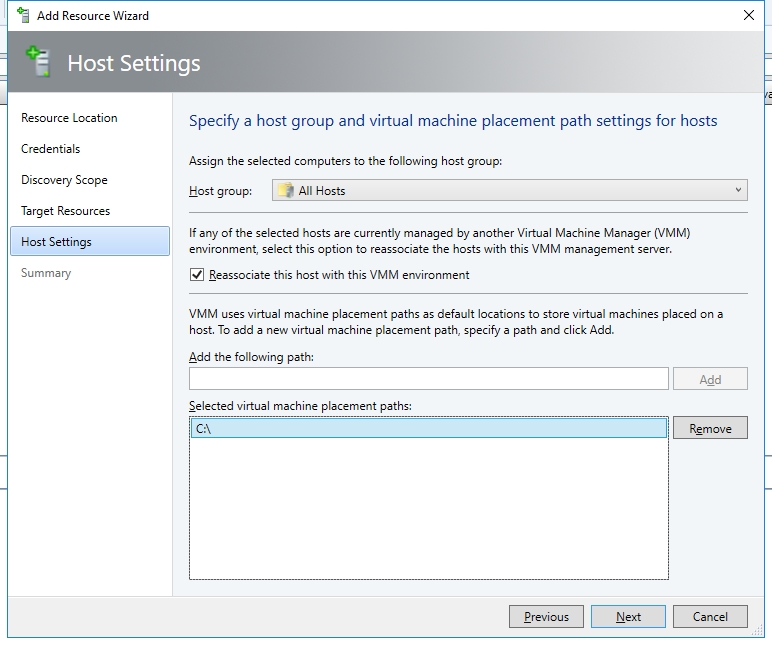
- Select the checkbox "Re-associate this host with this VMM environment" and add the C:\ as the VM placement path.
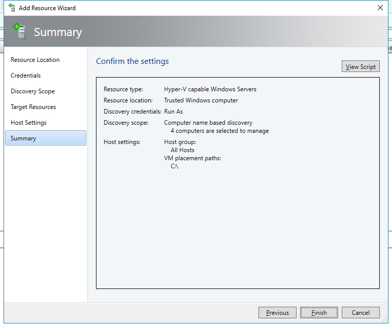
- On next page confirm the settings and click "Finish".
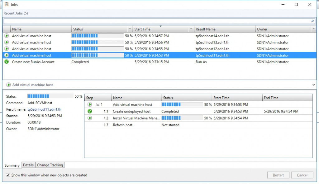
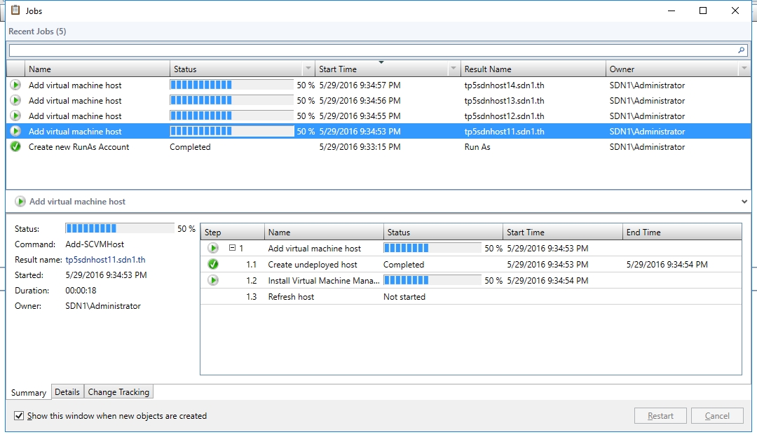
- Now you could see VMM is adding those Hyper-V hosts to the VMM environment.
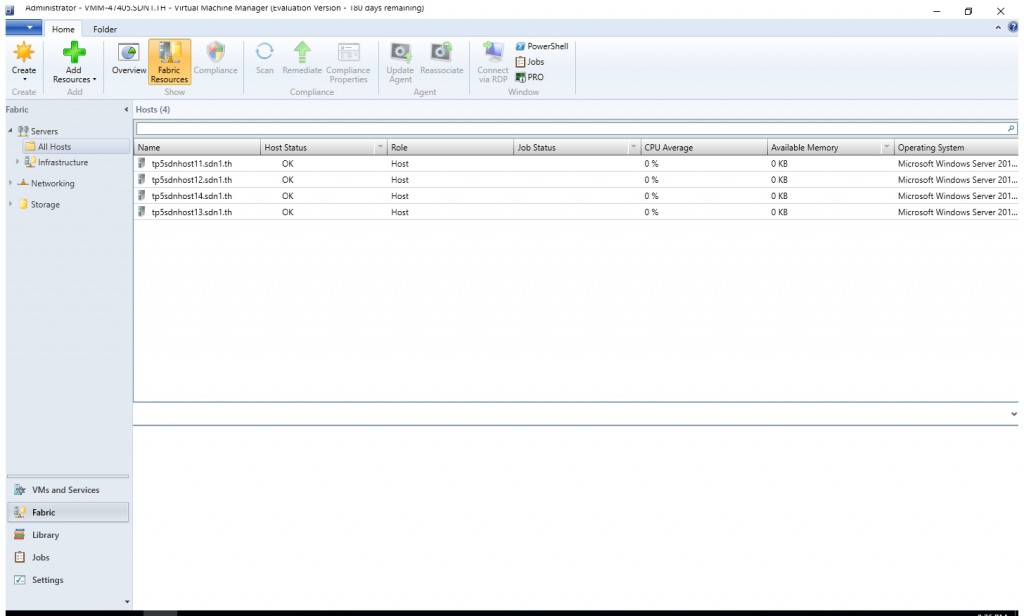
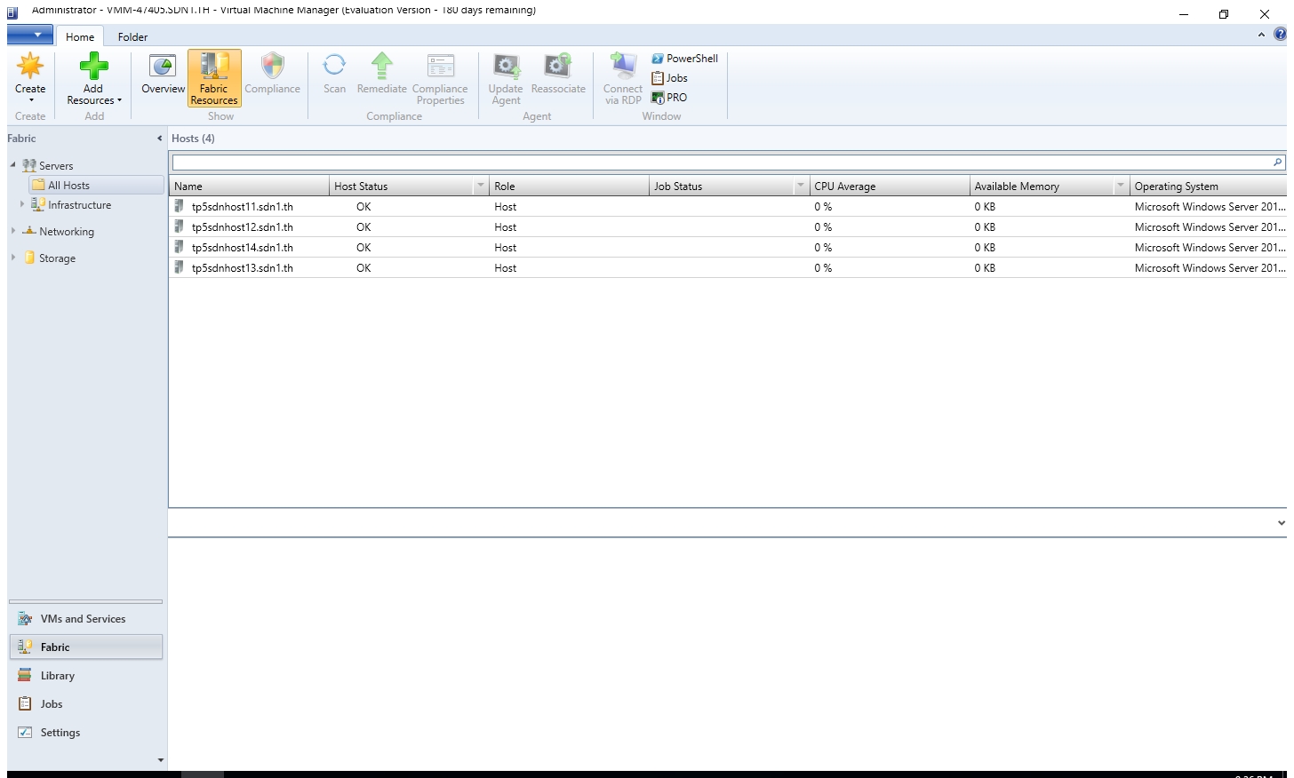
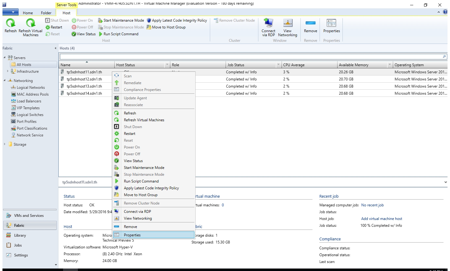
- After the above 4 jobs complete, you would see 4 Hyper-V hosts in the "All Hosts" group.
Create Logical Network and Logical Switch for "MGMT"
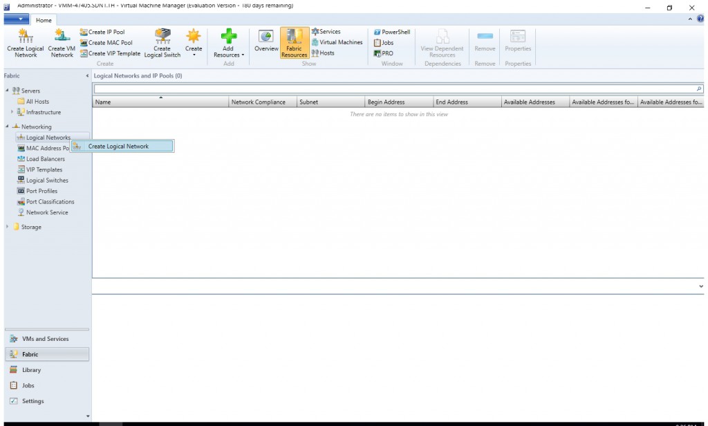
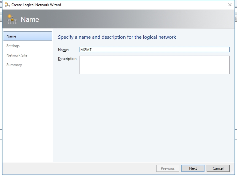
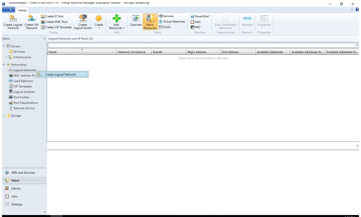
- Right click "Networking > Logical Network" and select "Create Logical Network".
- Type the name "MGMT".
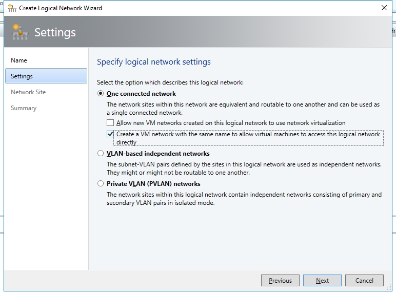
- Select the checkbox "Create a VM network with the same name to allow virtual machines to access this logical network directly.". Then click "Next".
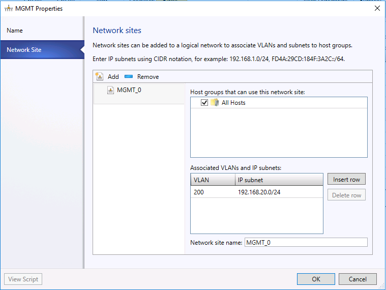
- Select the host group "All Hosts" and add the VLAN (ID=0, IP Subnet = 192.168.2.0/24).
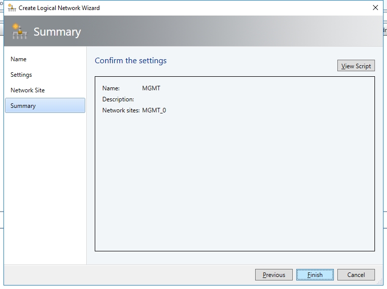
- Confirm the settings and click "Finish".
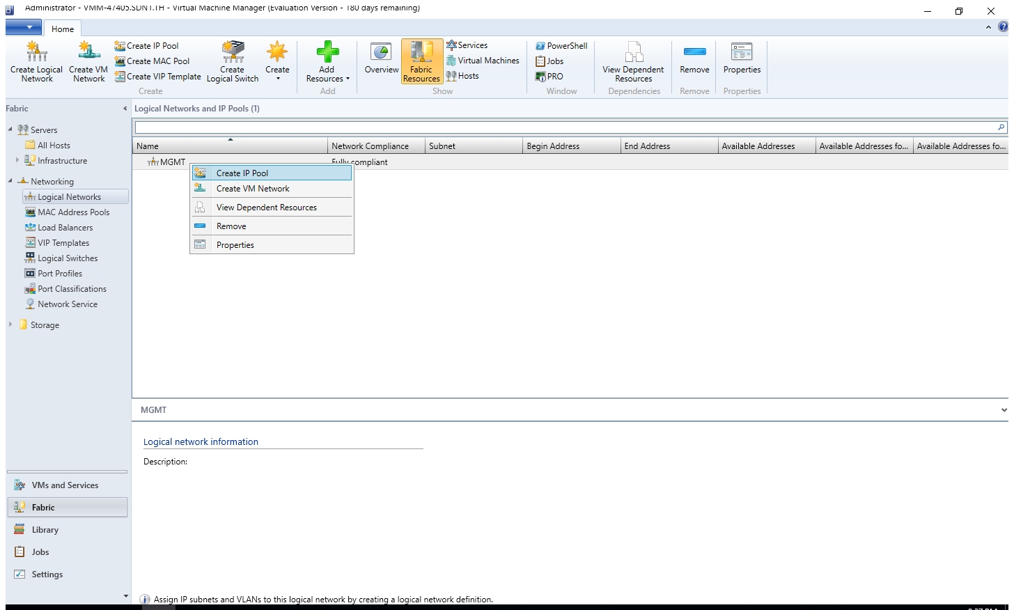
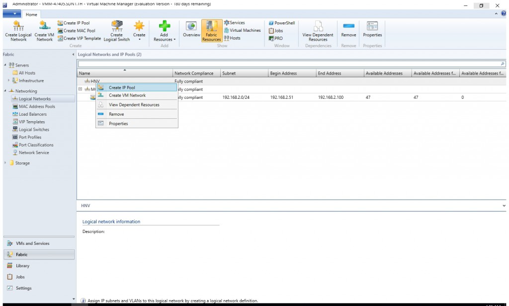
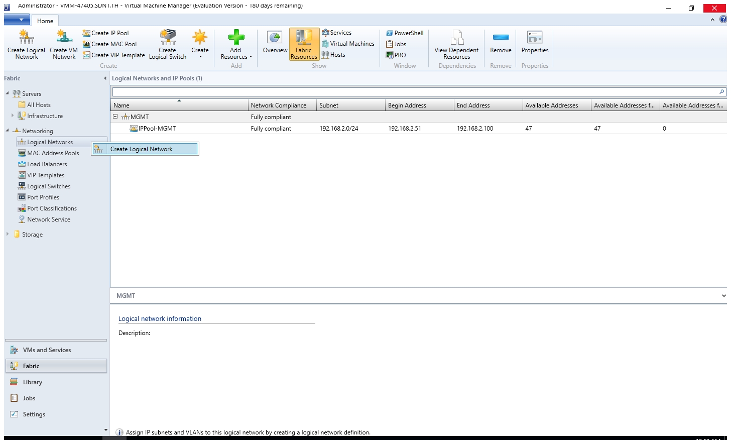
- Right click the logical network you just created. Select "Create IP Pool".
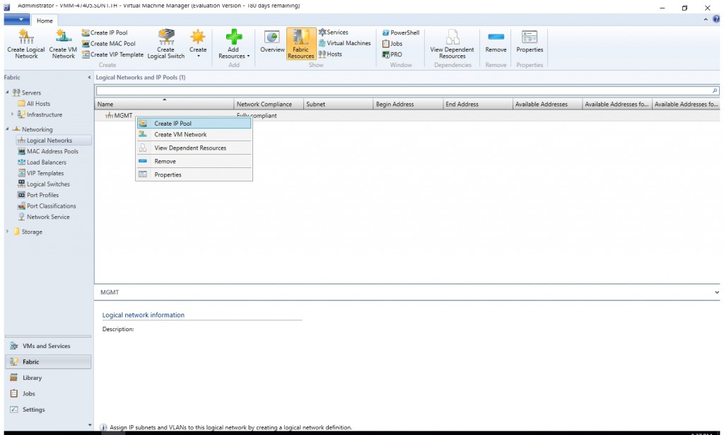
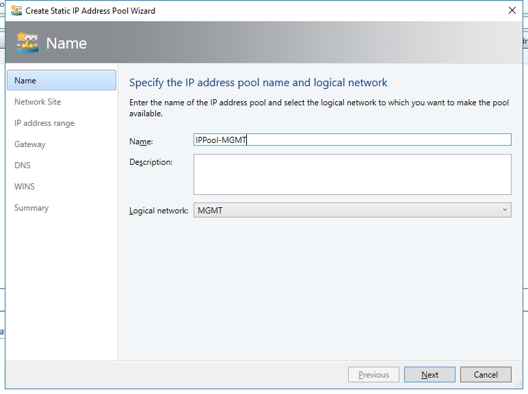
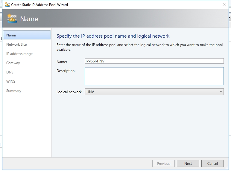
- Give it a name "IPPool-MGMT". Click "Next".
- Accept the default Network Site, click "Next".
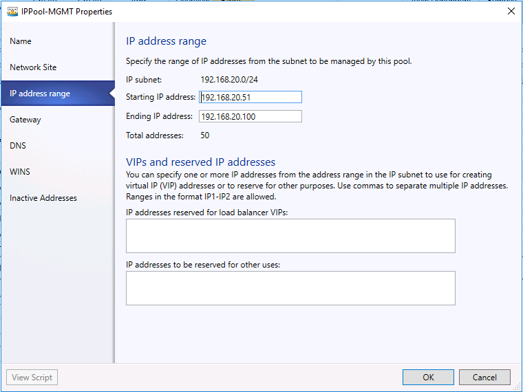
- Configure the IP pool start from 192.168.20.51 and end at 192.168.20.100. Then click "Next".
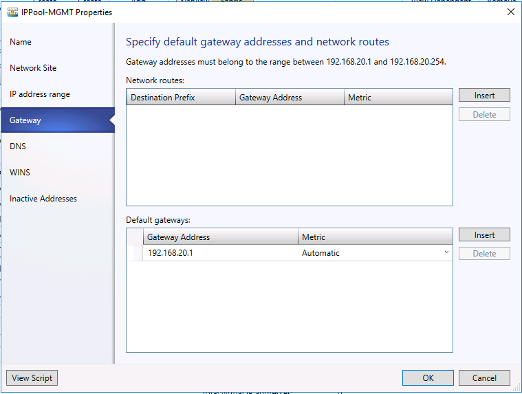
- Insert the default gateway address 192.168.20.1. Then click "Next".
- Insert the DNS server address 192.168.20.3. Then click "Next".
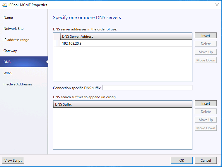
- You don't need specify WINS. Just click "Next" and confirm the settings on the next page. Last click "Finish".
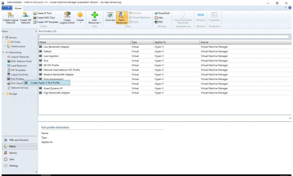
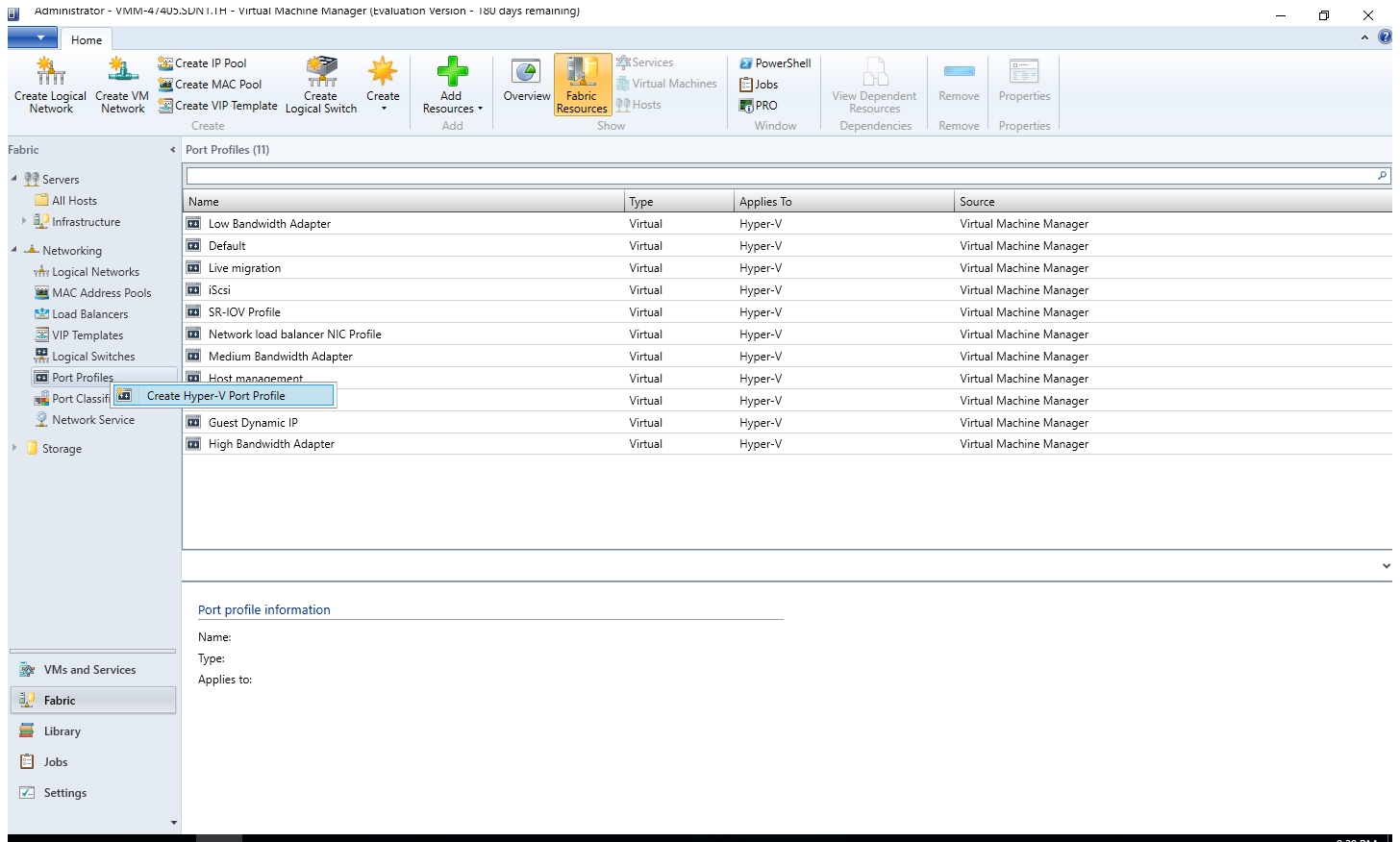
- Right click "Network > Port Profiles", select "Create Hyper-V Port Profile".
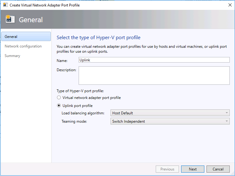
- Give it a name "Uplink-MGMT". Select the option "Uplink port profile".
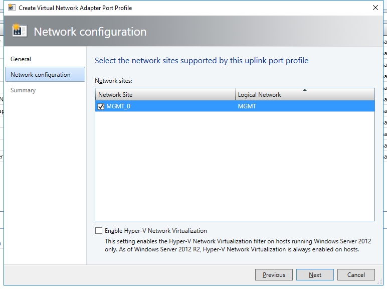
- Select the site "MGMT_0". DO NOT select the checkbox "Enable Hyper-V Networking Virtualization".
- On the confirm the settings page, click "Finish".
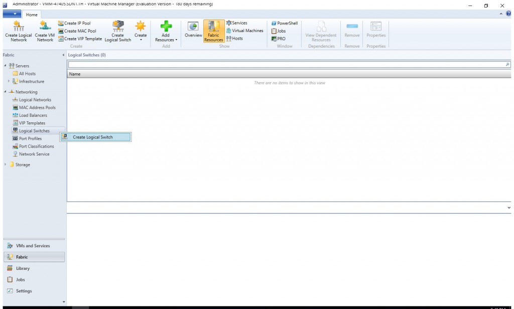
- Right click "Networking > Logical Switch" and select "Create Logical Switch".
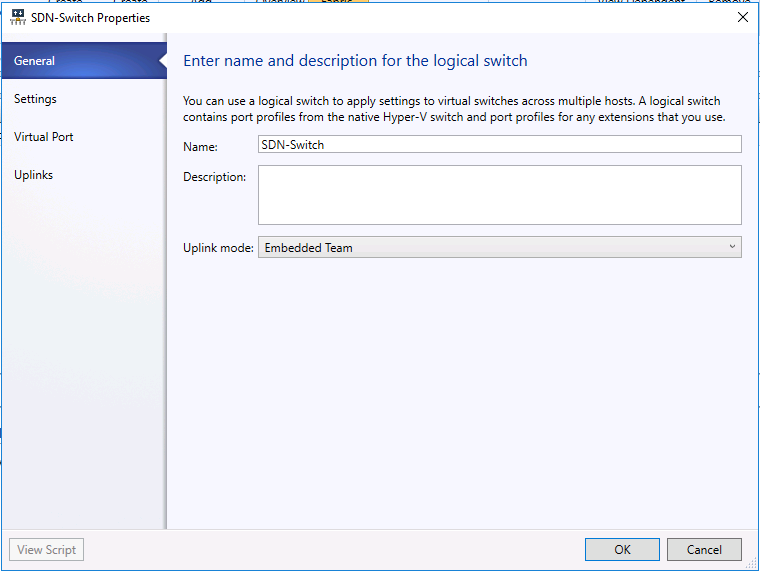
- Type the name "SDN-Switch" and Select Uplink mode "Embedded Team"
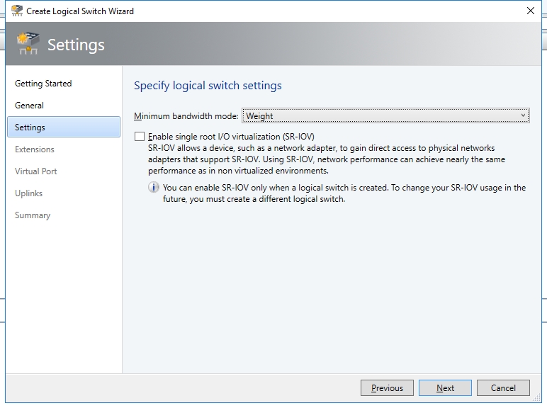
- On the next page, accept the default setting and click "Next".
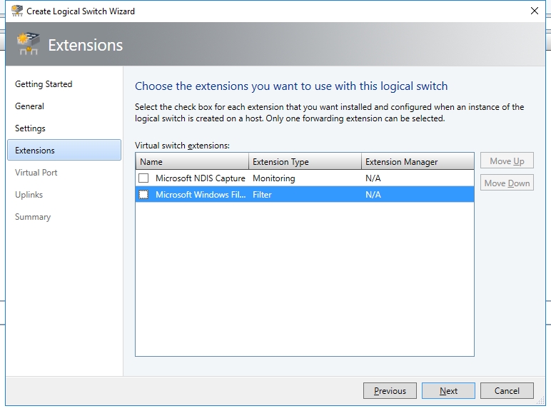
- Clear the checkbox "Microsoft Window Filtering Platform". New SDN stack uses Virtual Filtering Platform (VFP) from Azure instead of the default Windows Filtering Platform.
- In this test, I don't use any virtual port. So I skip the Virtual Port page.
- On the Uplink page, click "Add > Existing Uplink Port Profile".
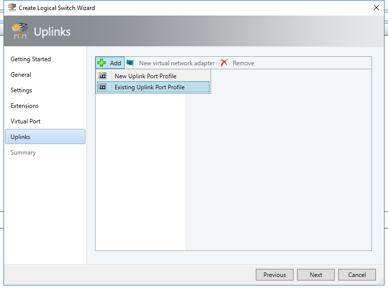
- Select the uplink profile we just created. It's Uplink-MGMT in my case.

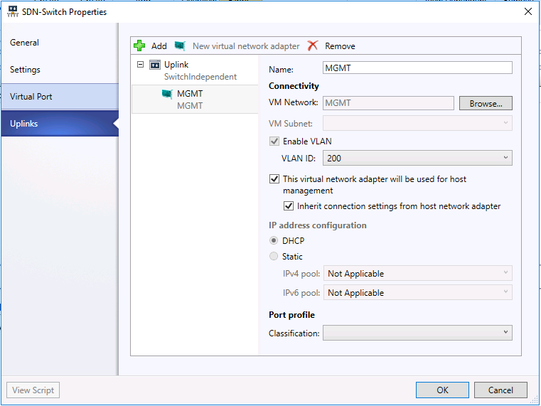
- Click the button "New Virtual Network Adapter". Type the name "MGMT". Select the checkbox "This virtual network adapter will be used for host management" and "Inherit connection settings from host network adapter". Since I have DHCP server available in the management VLAN, I selected "DHCP" as my IP address configuration. If you don't have DHCP, you may select "Static" and select the corresponding IP pool (e.g., "IPPool-MGMT").
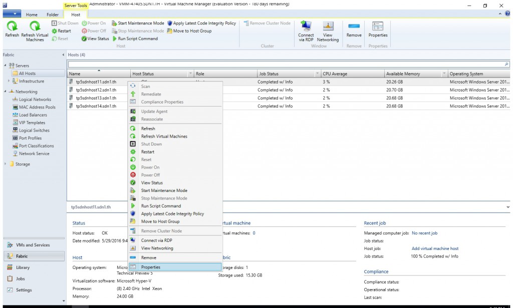
- Right click one of the Host and select "Properties".
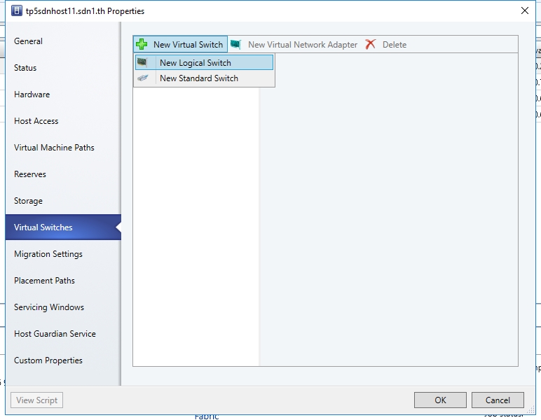
- Click "Virtual Switch" and click the button "New Virtual Switch". Then select "New Logical Switch".
- Bind the logical switch to the corresponding NICs. In my case, I have one NIC on the host. If you have multiple NICs, you may add them to the "Physical Adapters" list.
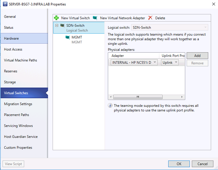
- Use the same procedure you may bind logical switch "SDN-Switch" to the rest hosts.
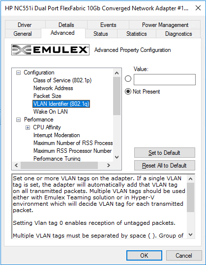
- Remove the VLAN ID from all the physical NICs which bind to the above logical switch.

Create NC Network Service
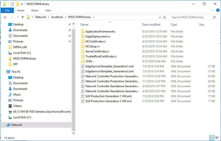
Copy a syspreped Windows Server 2016 image to the share folder of VMM VM \\localhost\MSSCVMMLibrary\VHDs. Volume License (VL) image is recommended. Otherwise you would have to modify the service template later and input the product key.
Download the SDN VMM template. Unzip the compressed file and copy the folder GW, NC and SLB to the share folder \\localhost\MSSCVMMLibrary\
Run the script below create a self-signed certificate and export two version of the certificate (cer and pfx) to C:\. Then copy the exported certificate files to the corresponding folders.
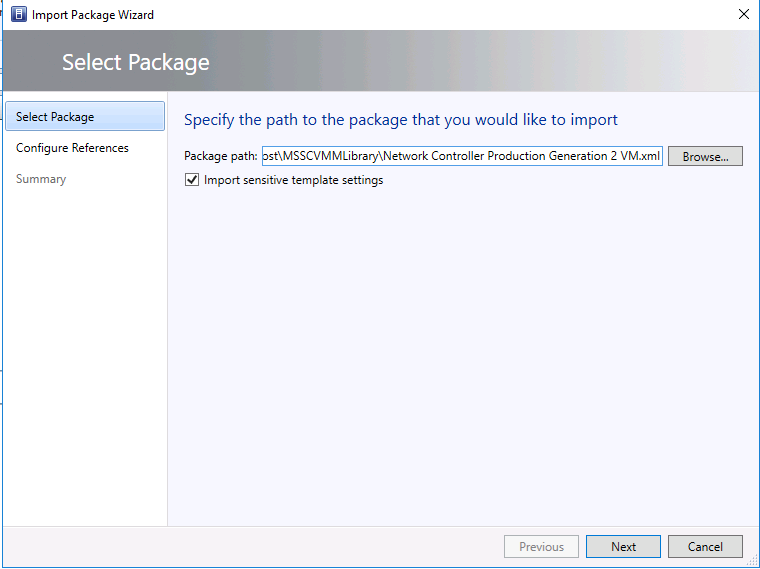
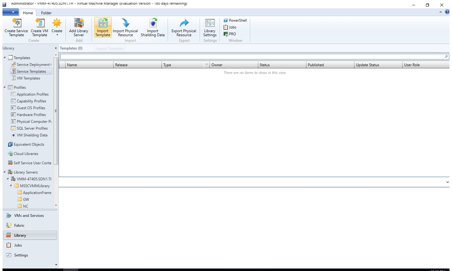
 $cert = New-SelfSignedCertificate -KeyUsageProperty All -Provider "Microsoft Strong Cryptographic Provider" -FriendlyName "MultiNodeNC" -DnsName @("192.168.2.34")
Export-Certificate -Cert $cert -FilePath c:\MultiNodeNC.cer
$PlainPassword = "123"
$SecurePassword = $PlainPassword | ConvertTo-SecureString -AsPlainText -Force
Export-PfxCertificate -Cert $cert -FilePath c:\MultiNodeNC.pfx -Password $securepassword -ChainOption BuildChain
copy C:\MultiNodeNC.pfx \\localhost\MSSCVMMLibrary\ServerCertificate.cr\
copy C:\MultiNodeNC.cer \\localhost\MSSCVMMLibrary\TrustedRootCertificate.cr\
copy C:\MultiNodeNC.cer \\localhost\MSSCVMMLibrary\NCCertificate.cr\
Click "Library" in VMM console and browse to "Template > Service Template". Click the button "Import Template"
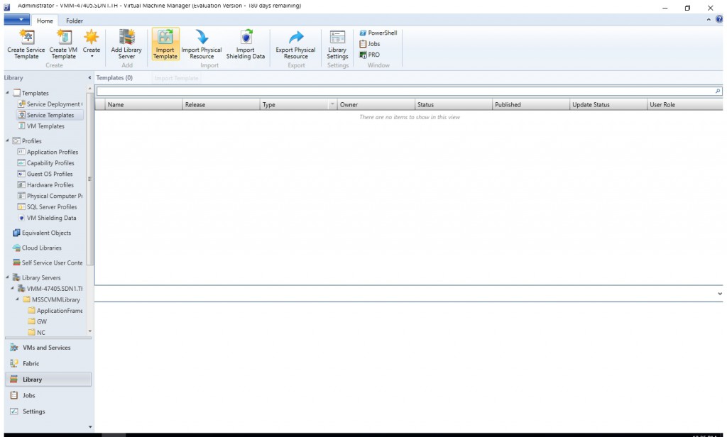
Browse to \\localhost\MSSCVMMLibrary\NC and select "Network Controller Production Generation 2 VM.xml". If you don't have 3+ compute nodes, you may select "Network Controller Standalone Generation 2 VM.xml" or "Network Controller Standalone Generation 1 VM.xml", which depends on your syspreped image is Gen 1 VM or Gen 2 VM.
On the Configure Reference page, map the WinServer.vhdx to the Syspreped image you copied to \\localhost\MSSCVMMLibrary\VHDs\. In addition, you may also need to map other resource to the corresponding folder under \\localhost\MSSCVMMLibrary\ if they were not recognize automatically.
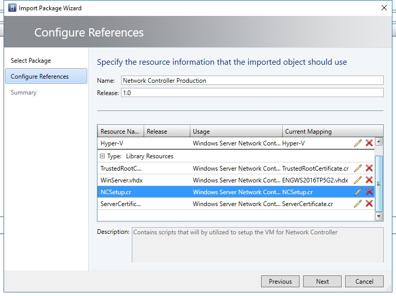
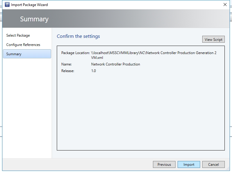
Then click the "Import".
If your syspreped image is based on Volume License image, you may jump to step 12.
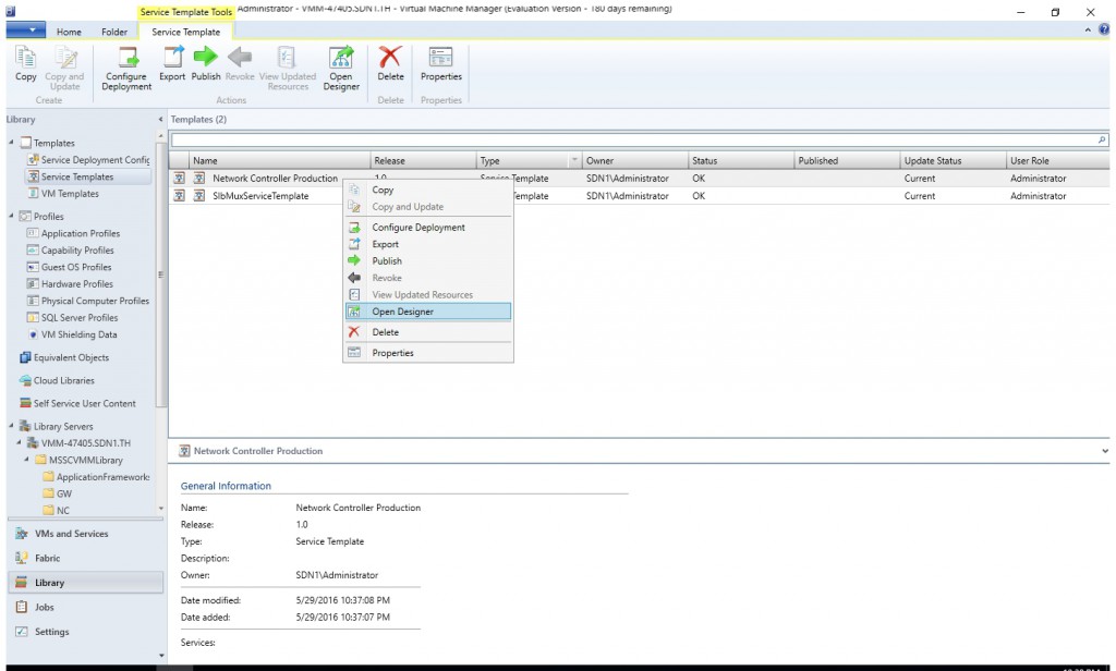
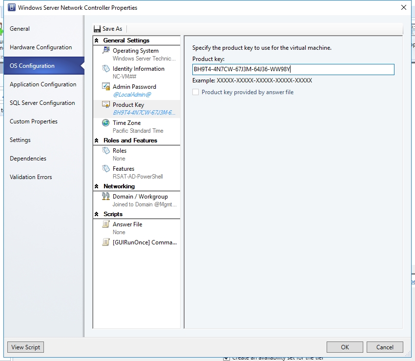
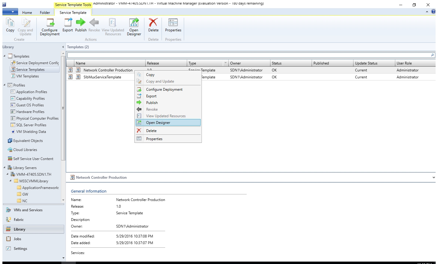
(Optional) If your syspreped image is not based on Volume License image, please right click the "Network Controller Production" and select "Open Designer".
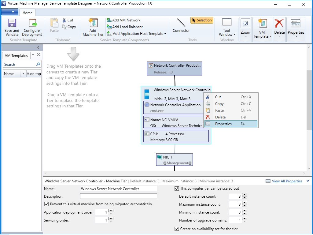
Right click the "Windows Server Network Controller" and select "Properties".

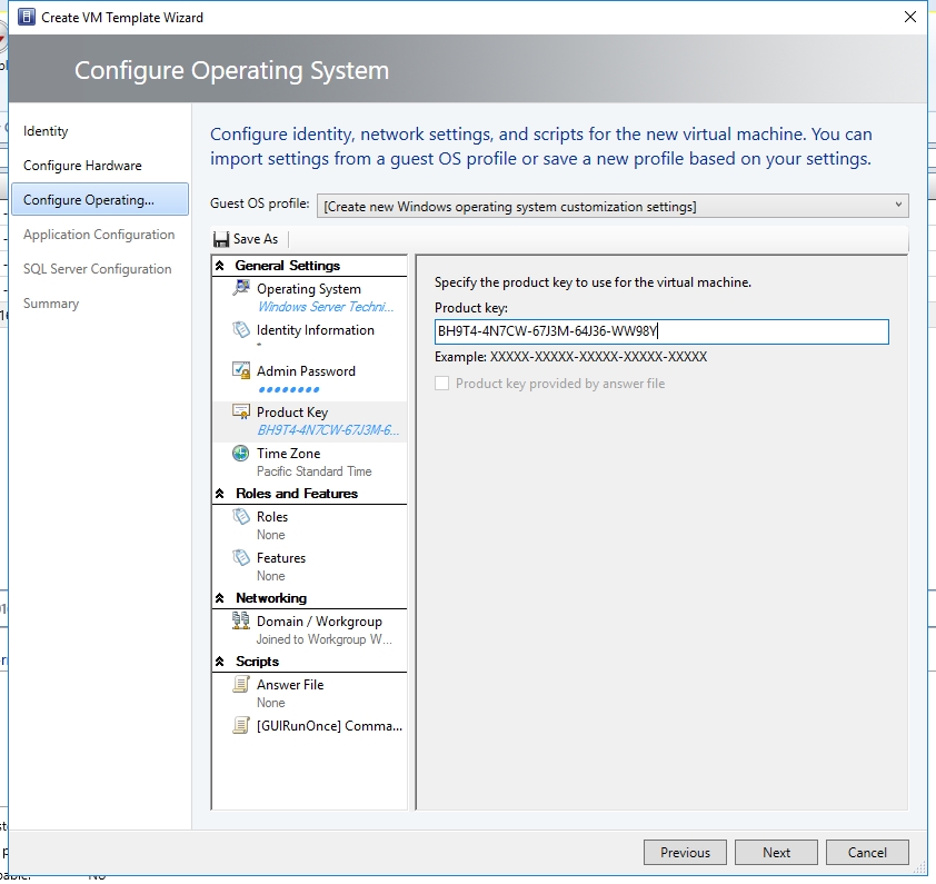
In Windows Server Network Controller Properties window, click "OS Configuration" and key in a valid product key or 6XBNX-4JQGW-QX6QG-74P76-72V67. If you are not using a Volume Licensed VHD\VHDX or if the VHD\VHDX is not supplied the Product Key using an Answer file, then the deployment will stop at the Product Key page during network controller virtual machine(s) provisioning.
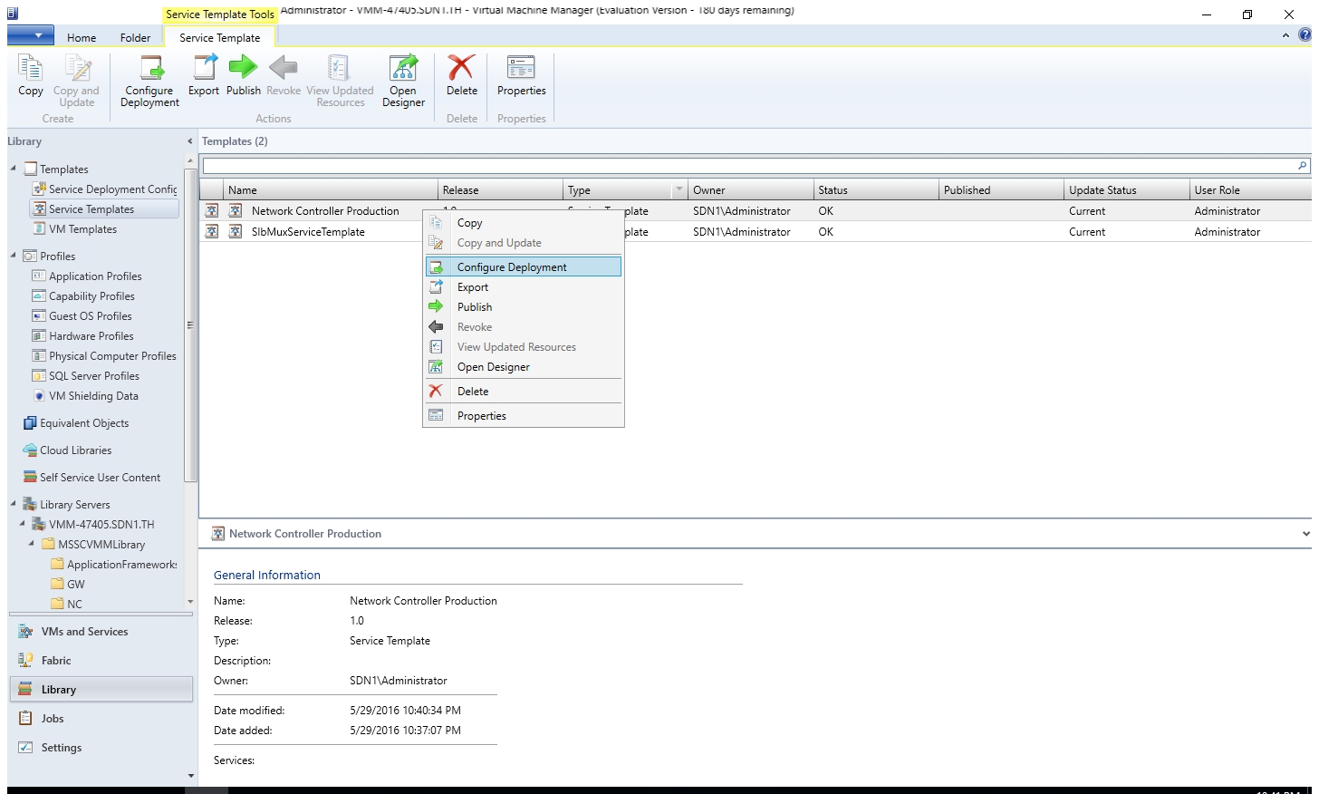
Right click the "Network Controller Production" and select "Configure Deployment".
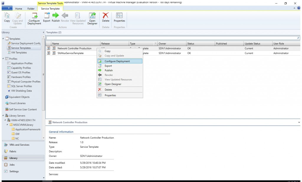
Type the name of the service. In this case, the name is "NC-VMM-RTM". Select the logical network "MGMT". Then click OK.
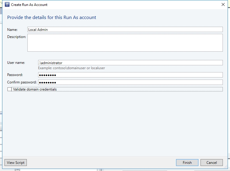
Configure the settings for the service deployment. For local Admin, you may need to create a new Run As account if you don't have one for local admin. The username is ".\administrator".
In my case, I didn't create security group for NC Client and NC Admin. I just used Domain Users group and Domain Admins instead. As for the diagnostic logging settings, they're optional. The important is the format of RestIPaddress is 192.168.20.34/24 instead of just IP address. The format of MgmtDomainAccountName is "<domainname>\<username>" instead of just "<username">.
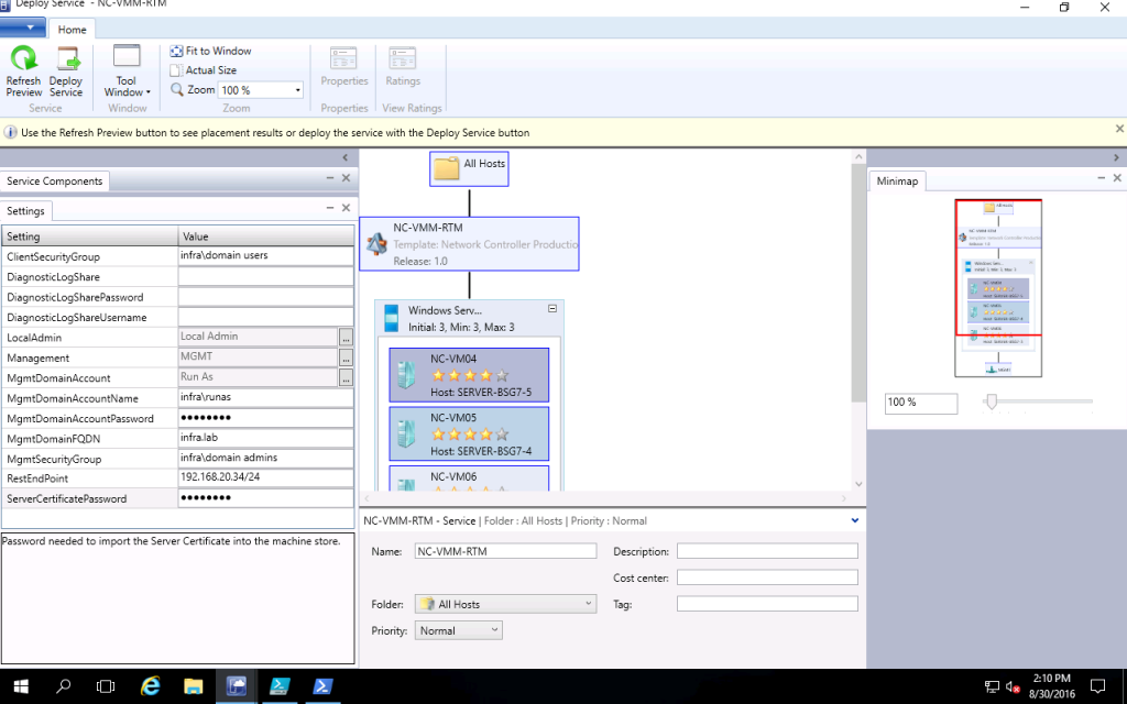
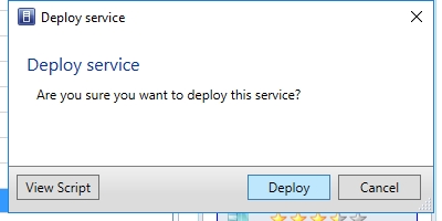
Then click the button "Refresh". Now you could click the button "Deploy Service".
In the prompt windows, click "Deploy".
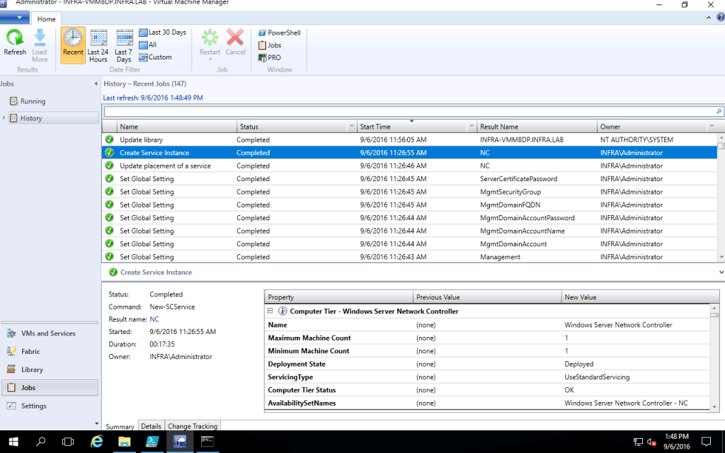
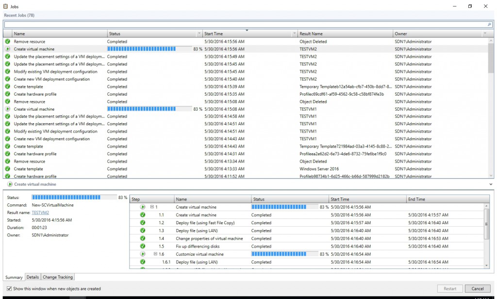
Later on you might find the deployment complete successfully.
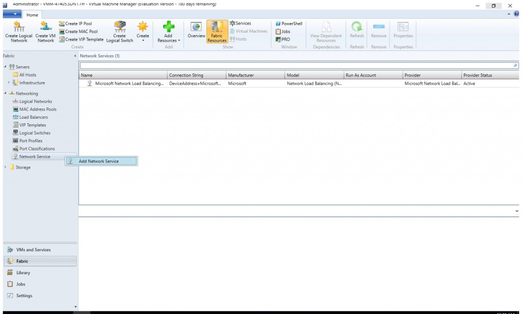
Click Fabric in the VMM console. Navigate to "Networking > Network Service". Right click "Network Service" and select "Add Network Service".
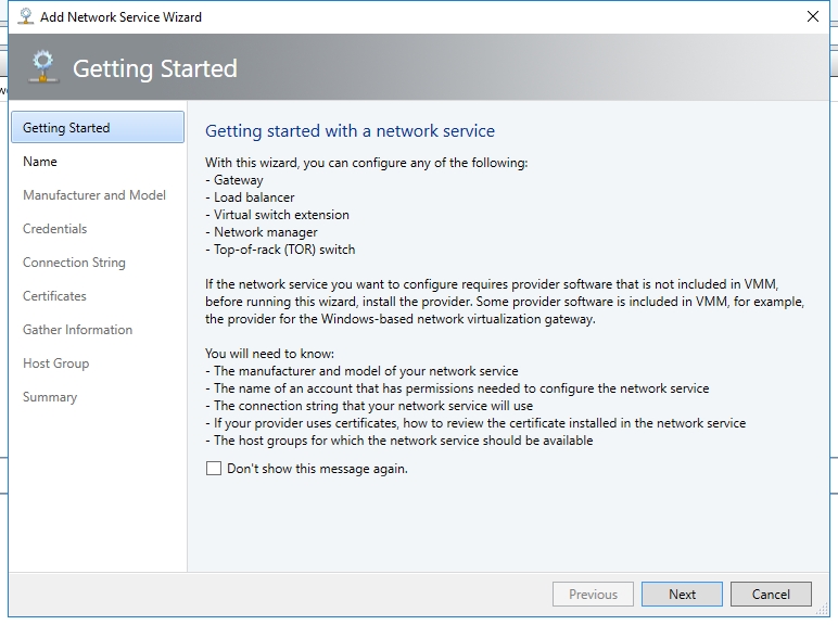
Click "Next" on the "Getting Started" page.
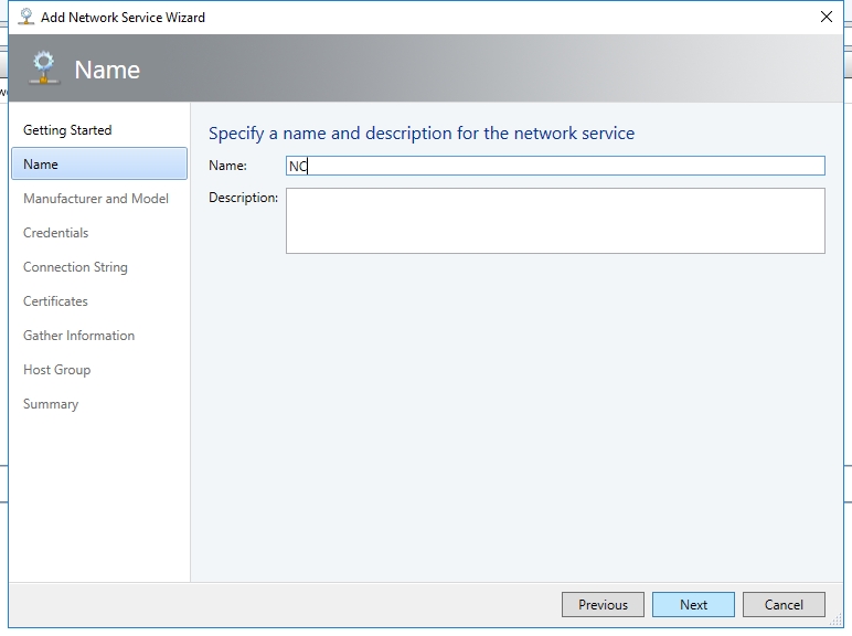
Give the network service a name, "NC" for example.
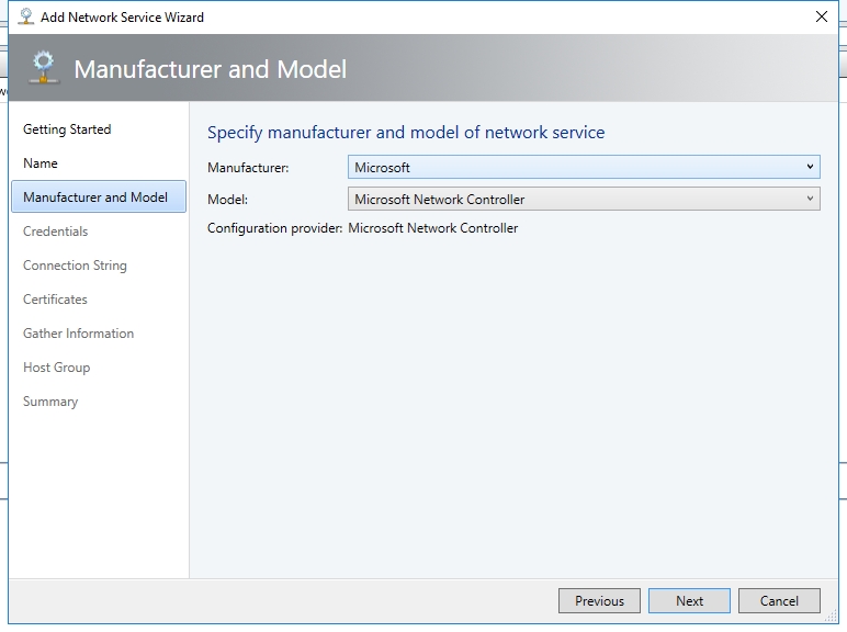
Select Manufacturer: Microsoft and Model: Microsoft Network Controller.
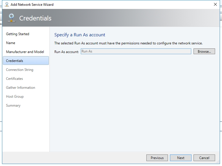
Still use "Run As" as the Run As account.
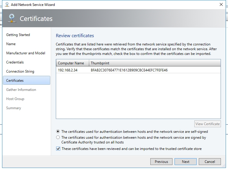
Connection String is
serverurl=https://192.168.20.34;SouthBoundIPAddress=192.168.20.34;servicename=NC-VMM-RTMOn the next page, select the checkbox "These certificate have been reviewed and can be imported to the trusted certificate store." Then click "Next"
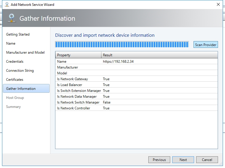
Click Scan Provider. Then click Next.
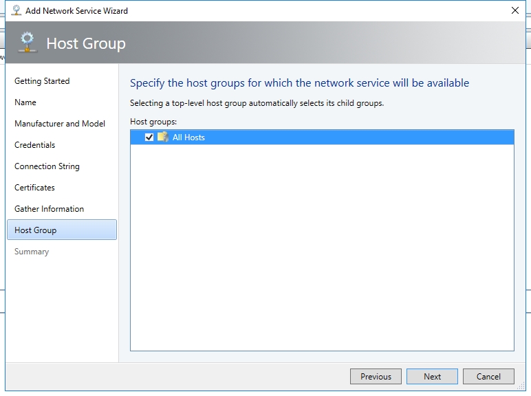
Select host group "All Hosts". Click "Next".
Click "Finish".
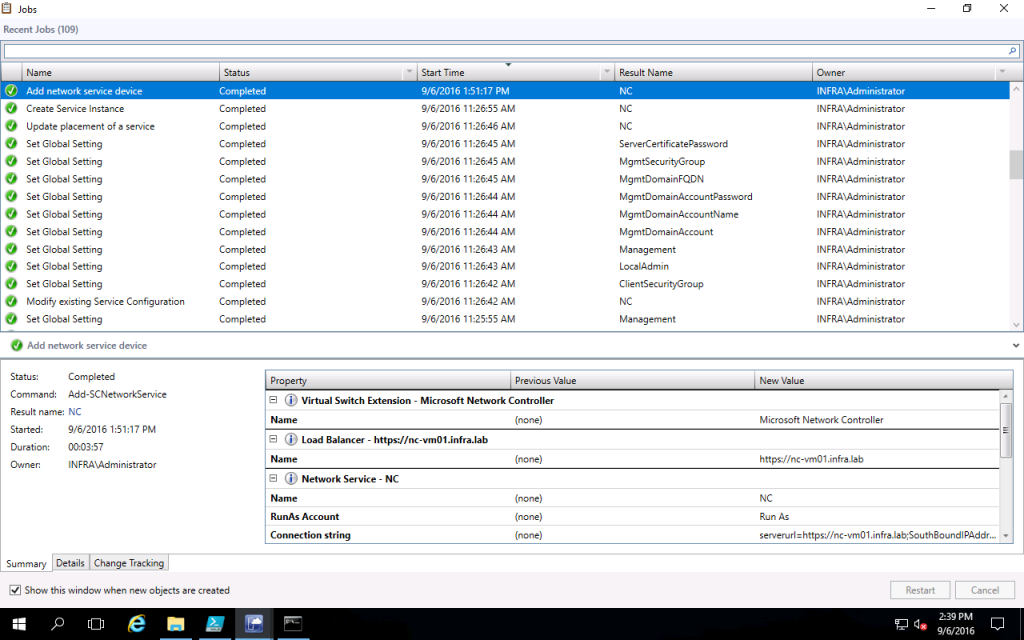
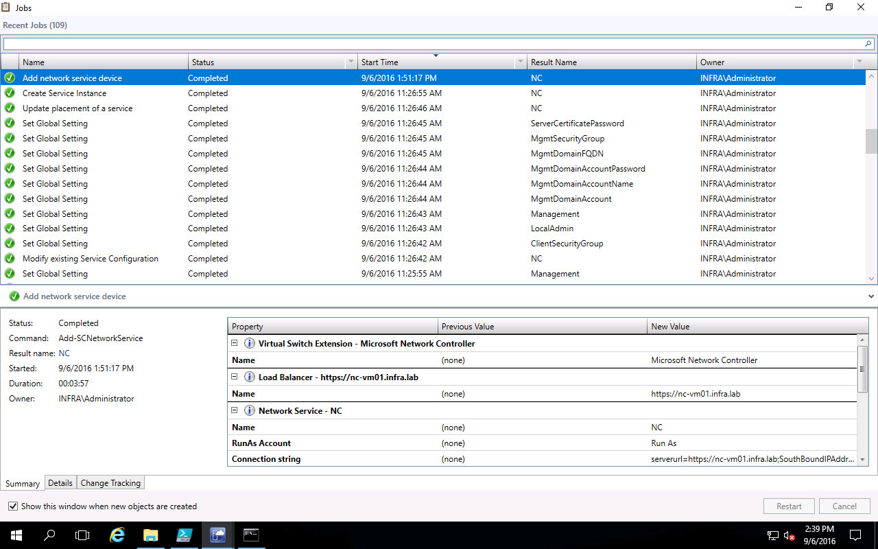
Please make sure the job "Add Network Service device" complete successfully.

Create Logical Network for "HNV"
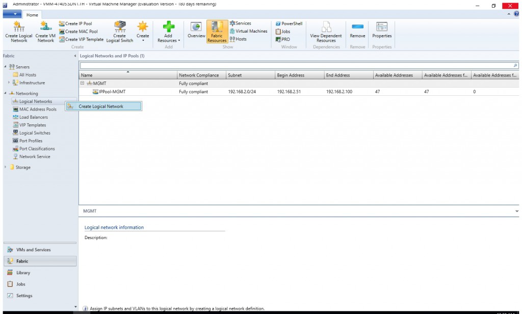
- Right click "Logical Network" and select "Create Logical Network".
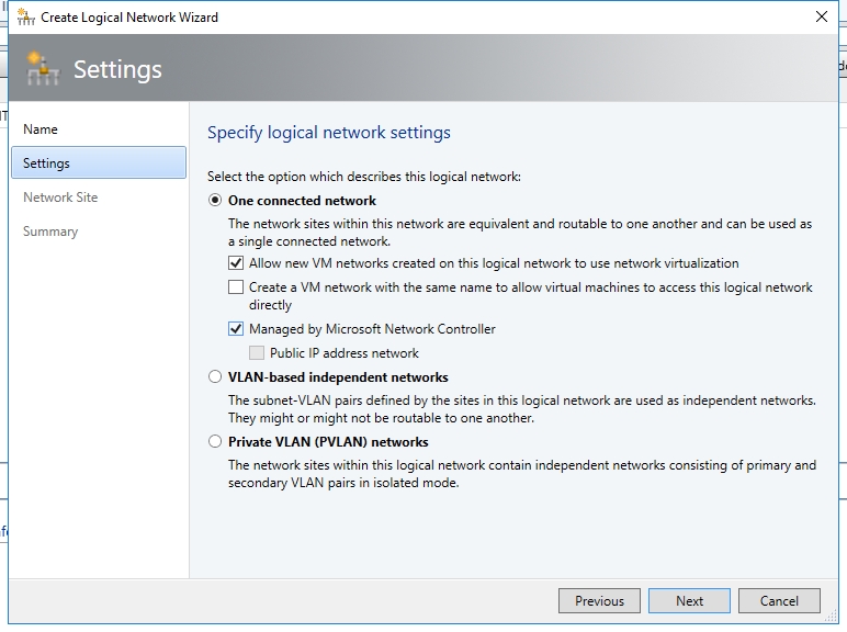
- Select the checkbox "All new VM networks created on this logical network to use network virtualization" and "Managed by Microsoft Network Controller".
- On the next page, associate the VLAN (ID=201, IP Subnet=192.168.21.0/24) to the logical network site.
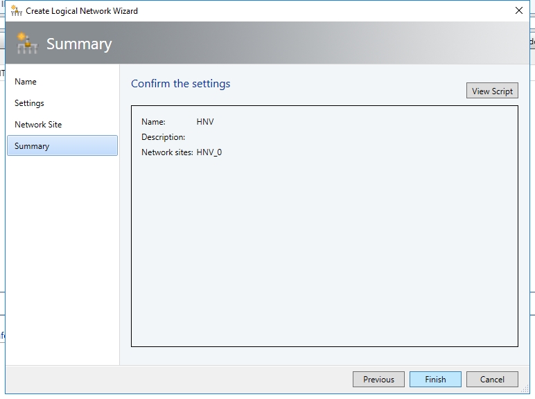
- Click Finish.
- Right click new created HNV logical network and select "Create IP Pool".
- Name is "IPPool-HNV". Click "Next".
- Accept the default Network Site, click "Next".
- Configure starting IP address as 192.168.21.51 and ending IP address is 192.168.21.100.
- Default gateway is 192.168.21.1.
- DNS server is 192.168.20.3.
- You don't need to configure WINS server. On the "Confirm the settings" page, click "Finish".
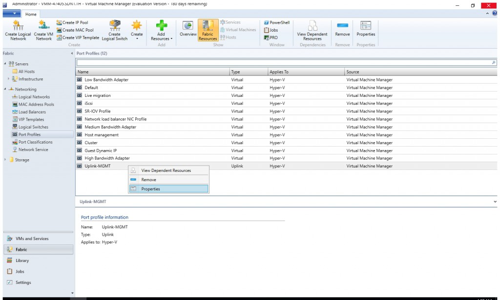
- Navigate to "Networking > Port Profiles". Right click the new created uplink profile and select Properties.
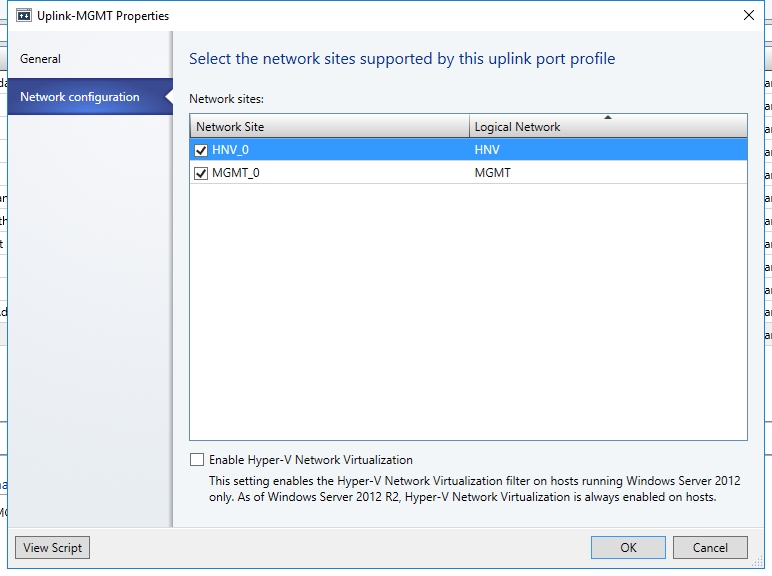
- Select the checkbox "HNV_0" to bind the network site "HNV_0" to the uplink profile, which means Hyper-V hosts will be able to access the logical network thru logical switch "MGMT-Switch".


Validation
Test Case 1: East-West Communication
- Click "VM and Services" in the VMM Console. Then right click "VM Networks" and select "Create VM Network".

- Give it a name "VNET-SLB".
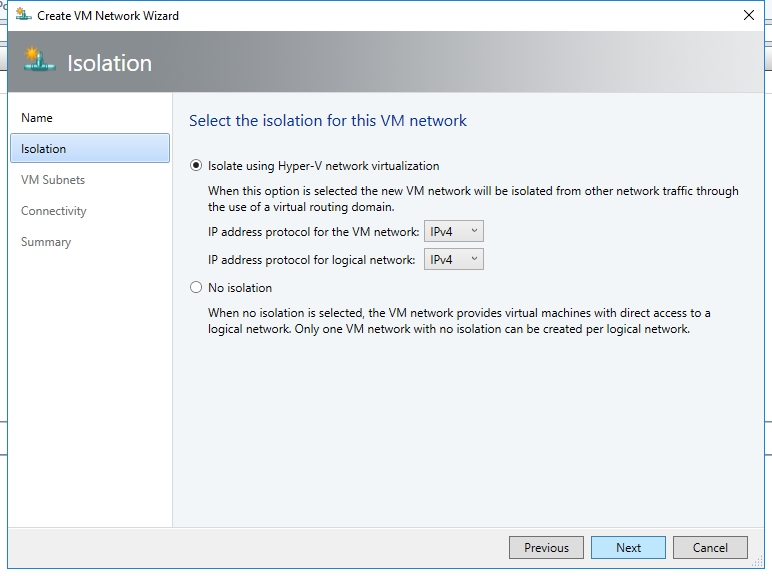
- Accept the default isolation setting and click "Next".
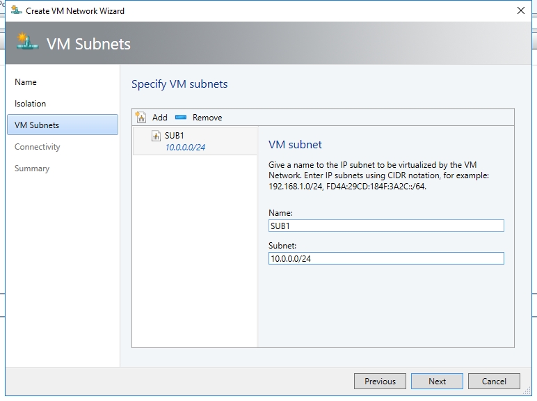
- Add a VM Subnet "SUB1" and set its subnet as "10.0.0.0/24". Then click "Next".
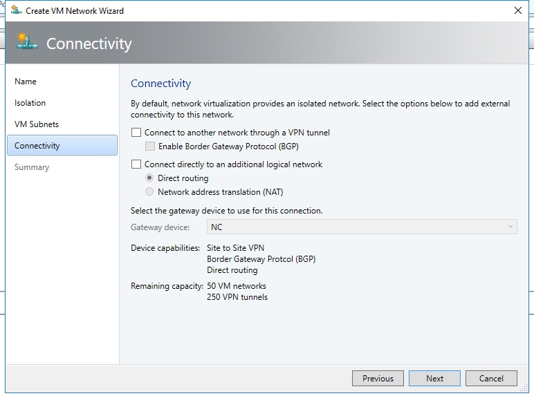
- Don't change the setting on "Connectivity" page at this moment. Click "Next".
- Click "Finish".
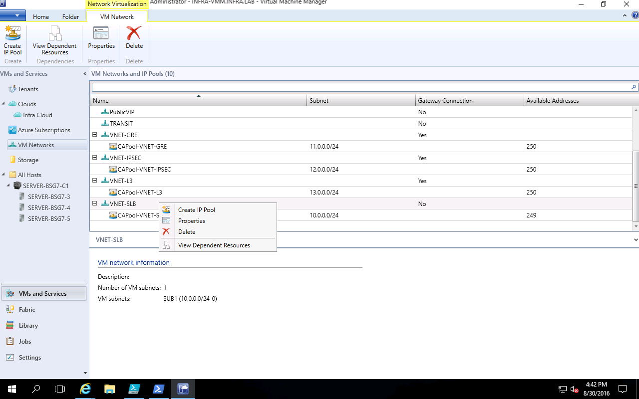
- Right click "VNET-SLB" and select "Create IP Pool".
- You may give it a name here (e.g., CATPool-VNET-SLB)
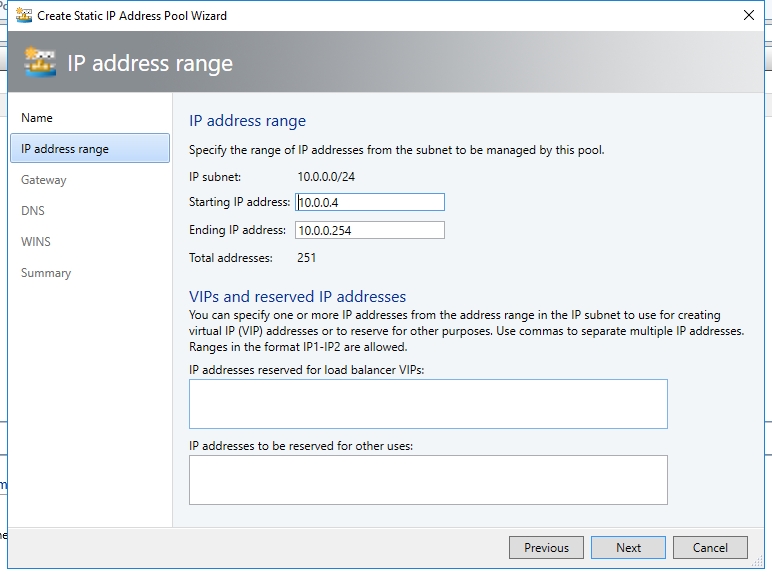
- Accept the default IP address space, click "Next".
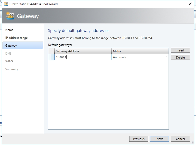
- Set default gateway to 10.0.0.1.
- Set DNS server to 192.168.20.3.
- You don't need to configure WINS server. Click "Next". On the "Confirm the settings" page, click "Finish".
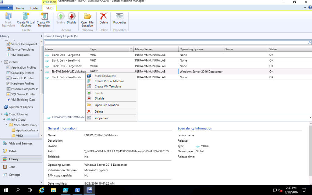
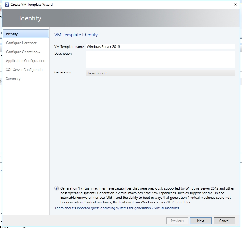
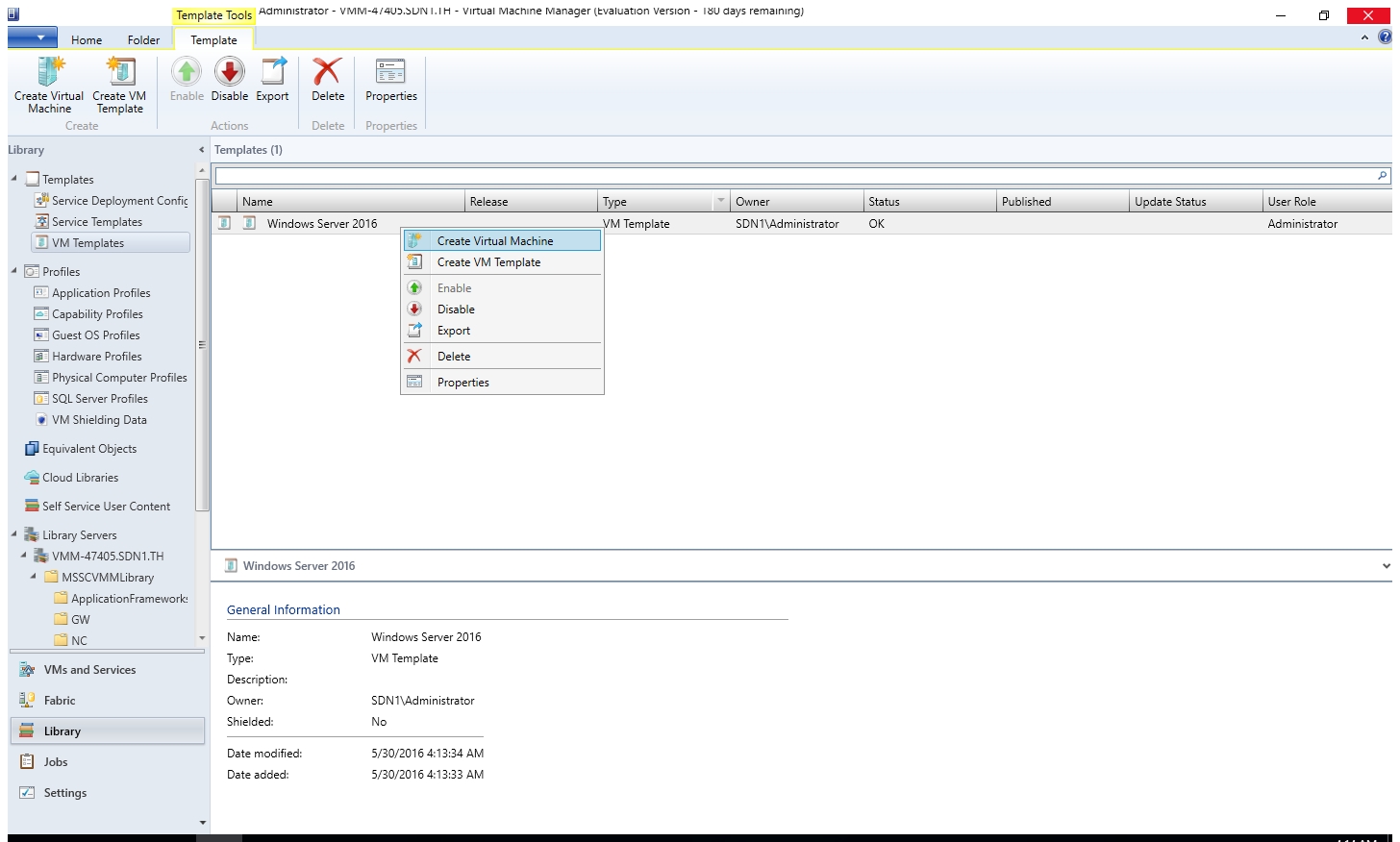
- Click "Library" in the VMM Console and navigate to "Library Servers > INFRA-VMM > MSSCVMMLibrary > VHDs". Right click the Syspreped Image you copied before and select "Create VM Template".
- Give the new VM template a name (E.g., "Windows Server 2016"). In my case, I used Gen 2 template. So I also select the generate 2. Click "Next".
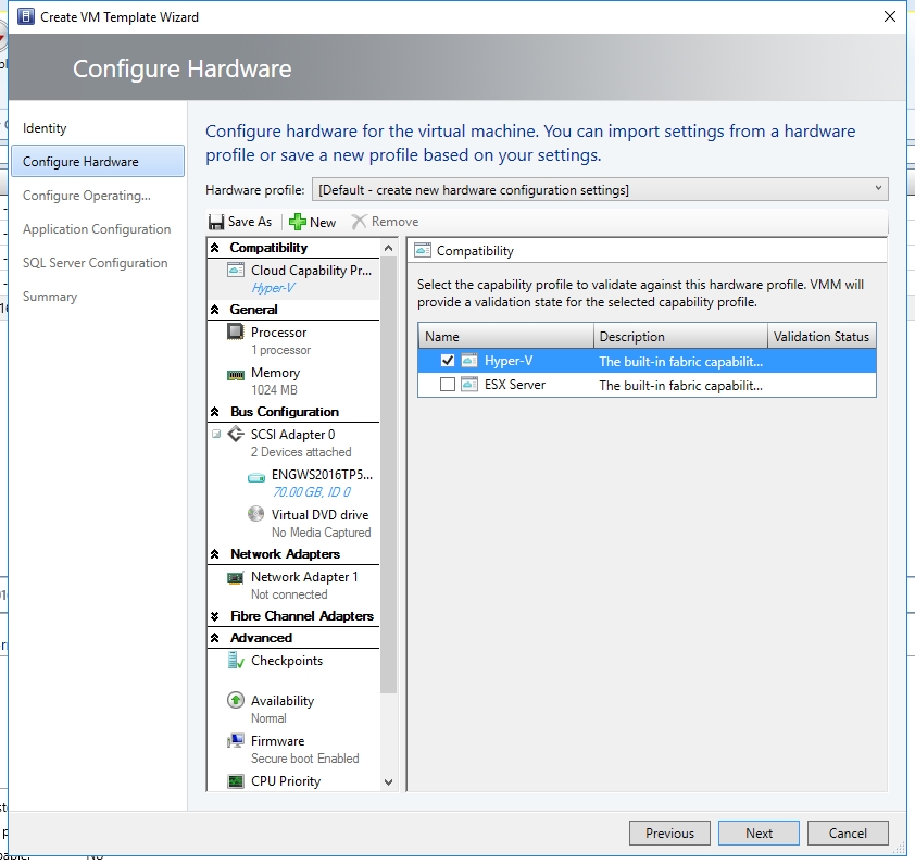
- On the Configure Hardware page, select Hyper-V as Cloud Capability.
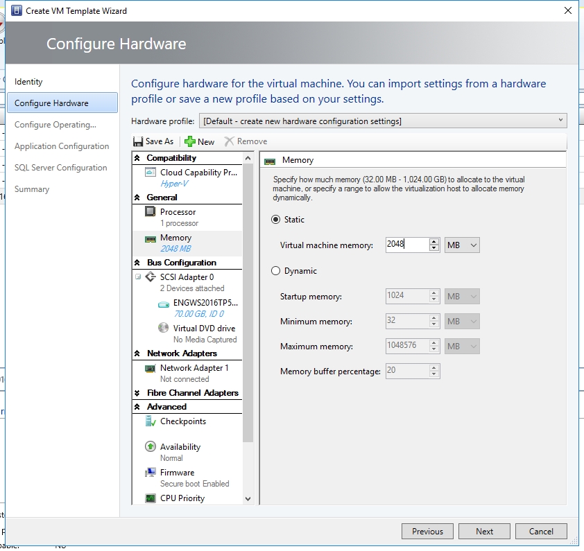
- Change the memory to 2048GB.
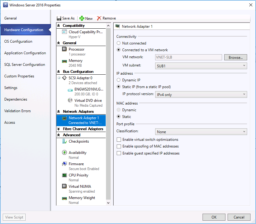
- Connect the above new create VM network "VNET-SLB" and subnet "SUB1".
- Configure the default password and product key.
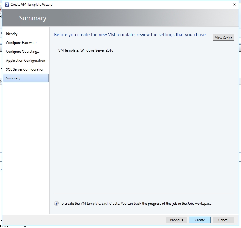
- Don't change any setting in the next two pages (Application Configuration and SQL Server Configuration). On the Summary page, click "Create".
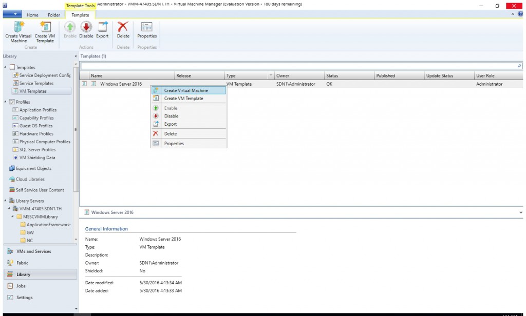
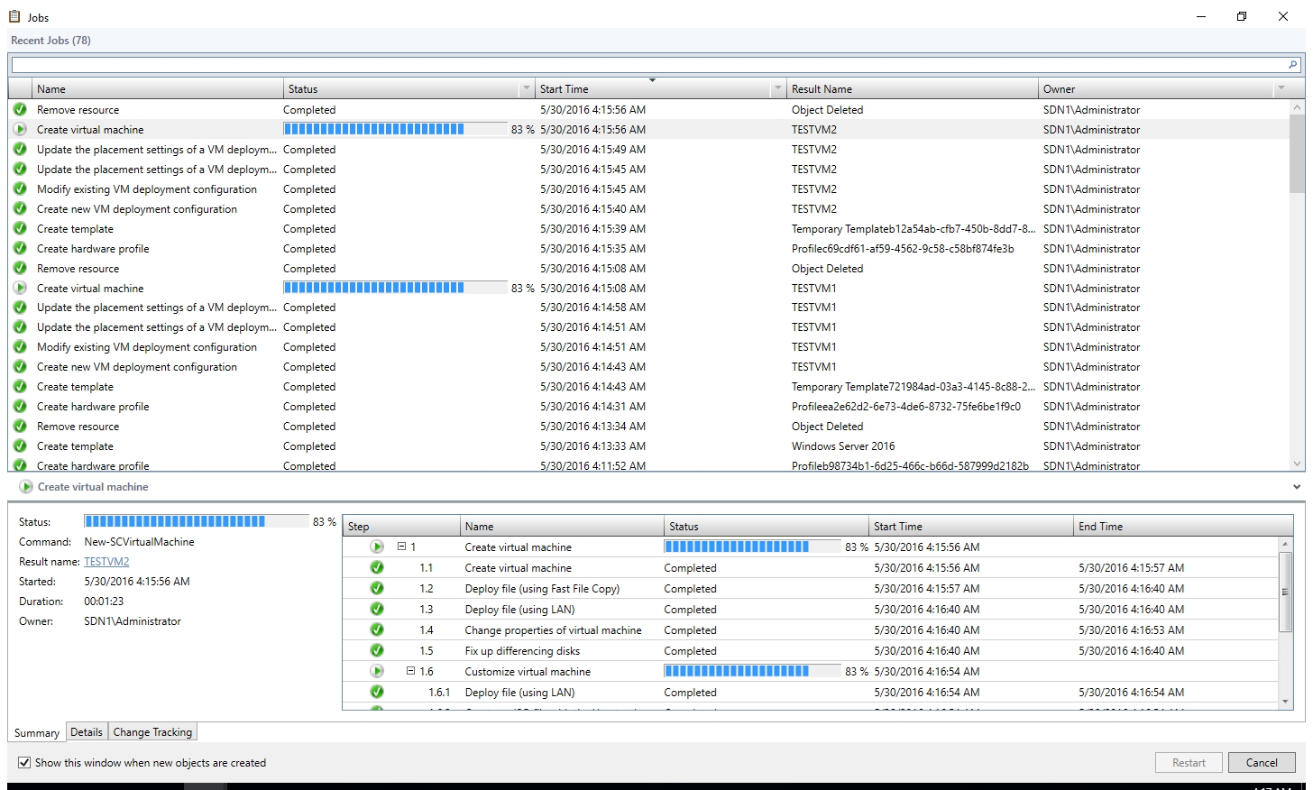
- Right click the new created VM template and select "Create Virtual Machine".
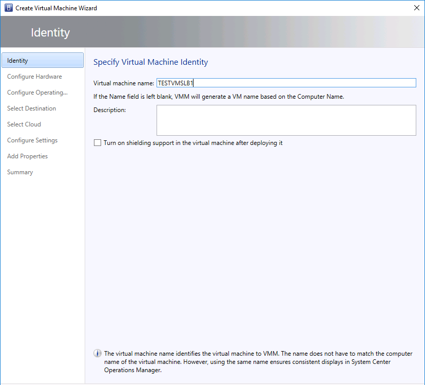
- Give the VM a name "TESTVMSLB1".
- Accept the default settings in all the rest pages in the wizard. On Summary page select checkbox "Start the virtual machine after deploying it". Then click "Create".
- Follow the same procedure to create another VM "TESTVMSLB2" in a different Hyper-V host.
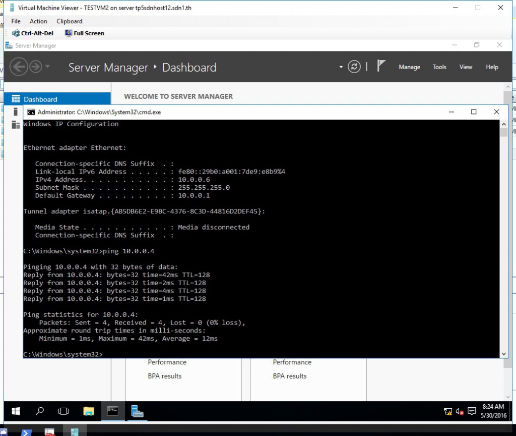
- After the above two VM provisioned successfully, you may connect them and disable the Windows Firewall (If your Syspreped image didn't disable it before). Then try to ping each other and make sure east-west communication is ok.
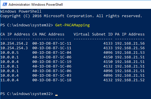
- You may run the cmdlet "Get-PACAMapping" on the host and make sure the PA address had already been assigned.


To Be Continued...
Now you had already deploy NC successfully with VMM. In the next post we will walk through the steps to deploy SLB and enable NAT for VMs.