Step-by-step for deploying a SDNv2 using VMM - Part 1
Overview
In this blog, I am sharing all the steps I used to create a demo or test environment of a SDNv2 on Windows Server 2016 so that you can experiment with some of the new technologies by yourself.
If you're not familiar with Software Defined Networking in Windows Server 2016 Technical Preview 5, you may want to review the following links first:
- Software Defined Networking (SDN)
- Plan Software Defined Networking
- Deploy Software Defined Networking
- Deploy a Software Defined Network infrastructure using VMM
Deployment Prerequisites
Hardware
Component |
Minimum: PC Server x2 (1 management node and 1 Compute Node) |
Recommended: PC Server x4 (1 management node and 3 Compute Node) |
Disk drives: Operating System |
1 OS disk with minimum of 300 GB available for system partition and VHD native boot (SSD or HDD) |
1 RAID1 OS disk with minimum of 300 GB available for system partition and VHD native boot (SSD or HDD) |
Disk drives: Storage Space |
1 DATA disk with minimum of 300 GB available for VM placement (SSD or HDD) |
1 DATA disk with minimum of 400 GB available for VM placement (SSD) |
Compute: CPU |
Support SLAT (Start from Intel Xeon 5500 or i3/i5/i7 or AMD Opteron 6100) |
Intel Xeon E5-v3 or v4 |
Compute: Memory |
32 GB RAM |
128 GB RAM |
Compute: BIOS |
Hyper-V Enabled (with SLAT support) |
Hyper-V Enabled (with SLAT support) |
Network: NIC |
1Gb/s NIC |
10Gb/S NIC support 802.1Q |
HW logo certification |
*If you don't have 3+ compute nodes, you can still validate the SDN functionalities and features except high availability of Network Controller, MUX and M+N gateway.
Operating System
Requirements |
|
Edition |
Windows Server 2016 Datacenter Edition. You can boot into VHDX, and then use as the base operating system for deployment. |
Install Method |
Boot into VHDX |
Domain joined? |
No |
Network
Switch
Requirements |
|
# of available port |
2+ |
Port Speed |
1Gb+ |
802.1Q VLAN |
Optional but Recommended |
# of VLAN |
Optional but recommend to have 4 VLANs (e.g., 200, 201, 300, 400) If you don't have VLAN, you may use VLAN "0" instead |
BGP |
Optional |
DHCP
Optional
Internet access
Optional
Logical Network Topology of the Demo Environment
Here is the logical network topology of my demo environment.
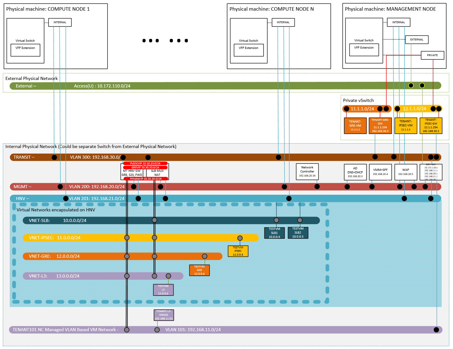
Physical Network
Internal Physical Network (Required)
All of the hosts (including management node and compute nodes) need to access at least one physical network. For testing or demo purpose, I would suggest use a separate physical network from your production environment. For example, it could be a couple of isolated VLANs or even a standalone switch. In my case, I have a dedicated Switch DELL PowerConnect 8024F for internal physical network.
Private vSwitch
The Private vSwitch was created on Management node, which is used to simulate the tenants' remote site. For example, 11.1.1.0/24 will have VM TENANT-GRE-GW and TENANT-GRE-VM. They are GRE gateway and test VM in the remote site. 12.1.1.0/24 will also have two VMs. They are TENANT-IPSEC-GW and TENANT-IPSEC-VM. Those two VMs will be used to test the IPSEC S2D connection.
External Physical Network (Optional)
This network is optional. In case you want to allow the infrastructure VMs and tenant VMs in the internal physical network accessing the external network (e.g., your corporate network, Internet, etc.), you may want to connect your management node to the external physical network. As for compute nodes, their connections to external physical network are optional coz they will be able to access the external physical network thru the BGPNAT VM on management node. Actually in the whole environment, only BGPNAT VM need to access external physical network directly. In my case, I have an external physical network, which is the corporate network.
VLAN
In a typical Software Defined Networking infrastructure, you have 4 nodes (Physical Machine) and those nodes need to access MGMT VLAN, HNV Provider VLAN and TRANSIT VLAN thru trunk port. (If want to use access port in the lab environment, you may use single NIC connect to the above 3 logical networks and all the VLAN IDs are 0. In that case, there is no any network isolation between those 3 logical networks.).
In my case, I used the following VLANs:
- VLAN 200: MGMT VLAN
- VLAN 201: HNV VLAN
- VLAN 300: TRANSIT VLAN
Besides the above three VLANs, I have a VLAN 101, which will be used as a NC managed VLAN based VM network in L3 gateway scenario. If you don't need to/want to validate the L3 gateway, you don't need that VLAN. There is a TEST VM "TENANT-L2-VM101" in the VM Network.
IP Subnets and Address Pools
Logical Network |
VLAN ID |
Subnet |
Address Pool |
MGMT |
200 |
192.168.20.0/24 |
191.68.20.51-192.168.20.100 |
HNV |
201 |
192.168.21.0/24 |
192.168.21.51-192.168.21.100 |
TRANSIT |
300 |
192.168.30.0/24 |
192.168.30.51-192.168.30.100 |
TENANT |
400 |
192.168.40.0.24 |
192.168.40.51-192.168.40.100 |
Public VIP |
0 |
10.10.10.0/24 |
10.10.10.51-10.10.10.100 |
Private VIP |
0 |
20.20.20.0/24 |
20.20.20.51-20.20.20.100 |
GRE VIP |
0 |
30.30.30.0/24 |
30.30.30.51-30.30.30.100 |
Infrastructure VMs
In my lab environment, I have the following infrastructure VMs. You also need to get these VMs ready before deploy SDN.
- BGPNATVM (INFRA-BGPNAT) -- The VM has three roles in the lab. First, it's the default gateway for all of the three compute nodes (Hyper-V hosts) and all the VMs except NATBAP VM itself. Second, optionally it's the NAT gateway and connect Internal Physical Network and External Physical Network. Last but the most important, it's also BGP router and will be used to build the BGP connection to MUX nodes and Gateway nodes. We will configure the BGP router and peers later. At this moment, you only need to install RRAS and configure NAT and static route among 3 logical networks (MGMT, HNV Provider and TRANSIT). In my setup, its vNIC as configured as below.
vNIC ID
vSwitch
VLAN ID
IP Address
Default Gateway
DNS Server
0
External-Network
n/a
DHCP
DHCP
DHCP
1
Internal-Network
200
192.168.20.1/24
n/a
n/a
2
Internal-Network
201
192.168.21.1/24
n/a
n/a
3
Internal-Network
300
192.168.30.1/24
n/a
n/a
4
Internal-Network
101
192.168.11.1/24
n/a
n/a
- DC (INFRA-DC) -- The VM is the DC and DNS. In my case, the domain name is infra.lab and DC's IP address is 192.168.20.3. Optionally, you may add DHCP role to the VM and simplify the rest of the deployment and configuration. In my setup, its vNIC as configured as below.
vNIC ID
vSwitch
VLAN ID
IP Address
Default Gateway
DNS Server
0
Internal-Network
200
192.168.20.3/24
192.168.20.1
127.0.0.1
- VMM (INFRA-VMM) -- The VM need to join the domain (in my case, it's infra.lab). You need to install SQL server, VMM and SPF on this VM. Please be informed that SPF is optional. If you want to leverage WAP providing the self-service experience for Virtual Network provision and management, you would need SPF. Deploy SQL, VMM and SPF is out of scope of this series of blogs. In my setup, its vNIC as configured as below.
vNIC ID
vSwitch
VLAN ID
IP Address
Default Gateway
DNS Server
0
Internal-Network
200
DHCP
DHCP
DHCP
- WAP (INFRA-WAP) -- The VM host all the WAP components. If you don't plan to/want to test the self-service capabilities of new SDN stack, you don't need this VM. Deploy and Configure WAP is out of scope of this series of blogs. In my setup, its vNIC as configured as below.
vNIC ID
vSwitch
VLAN ID
IP Address
Default Gateway
DNS Server
0
Internal-Network
200
DHCP
DHCP
DHCP
- Other Infrastructure VMs -- Network Controller, MUX and Gateways will be deployed thru VMM templates. We will cover those topics in the other posts.
Tenant VMs and VM Networks
In the above diagram, you may also find some tenant VM Network and TEST VMs. They will be used for the corresponding test scenarios.
Scenario |
VM Network |
VM |
East-West Communication |
VNET-SLB |
TESTVMSLB1, TESTVMSLB2 |
SLB |
VNET-SLB |
TESTVMSLB1, TESTVMSLB2 |
IPSec S2S VPN |
VNET-IPSEC |
TESTVMIPSEC |
GRE Tunnel VPN |
VNET-GRE |
TESTVMGRE |
L3 Routing |
VNET-L3 |
TESTVML3 |
Prepare Computer Nodes (Hyper-V HOSTs)
Prepare OS
Create a bootable VHD from Windows Server 2016 ISO/WIM. You may use Convert-WindowsImage.ps1 (https://gallery.technet.microsoft.com/scriptcenter/Convert-WindowsImageps1-0fe23a8f) to create such VHD. I also wrote a script (https://github.com/ostrich75/PrepareVHD), which can help you create and boot from that VHD with RDP enabled. In that way, you don't need to have the access to servers' consoles for remote KVM. Here is the example of how to use the script.
Examples:
.\PrepareVHD.ps1 -ImagePath I:\sources\install.wim -VHDxPath F:\VHDBOOT
Configure NIC
Configure the VLAN setting of one of the NICs which connect to the internal physical network*. If you have multiple NICs connect to that network, you only need to configure one at this moment. Later on, we will bind them to the logical switch and enable Switch Embedded Teaming thru VMM.
**According to Physical Network Configuration, the physical network adapters on the compute host must not have any VLAN filtering activated. So I have to use access port. Here is my logical network diagram.
Join Domain
Last join them to the above domain (in my case, it's "infra.lab".).
Notes and disclaimers:
- A certain familiarity with Windows administration and configuration is assumed.
- If you are asked a question or required to perform an action that you do not see described in these steps, go with the default option.
- There are usually several ways to perform a specific configuration or administration task. What I describe here is one of those many ways. It's not necessarily the best way, just the one I personally like best at the moment.
To be continued...
Next we will follow the guide Deploy a Network Controller using VMM.