Hyper-V: Clustering & Resiliency. Step 3: Networking Part 2
Hello Folks,
This is the 4nd post in our Hyper-V 2012 R2 from the ground up series. Last week we covered setting Host Configuration using SCVMM 2012 R2 and Clustering & Resiliency – Storage. Earlier this week we covered networking.
Today we keep building our environment. In our “from the ground up” series we are working towards highly available Hyper-V cluster that will support our workloads and that we will manage using SCVMM. We have our servers, storage, and our NIC teams and virtual Switches. Now we will create and configure our Virtual Networking.
A logical network is used to organize and simplify network assignments for hosts, virtual machines and services. As part of logical network creation, you can create network sites to define the VLANs, IP subnets, and IP subnet/VLAN pairs that are associated with the logical network in each physical location.” they can be used to describe networks with different purposes, create traffic isolation and even support traffic with different types of service-level agreements.
As logical networks represent an abstraction of the underlying physical network infrastructure, It enables you to model the network based on business needs and connectivity properties. Users can assign VM networks, which use logical networks for the physical connectivity, as part of virtual machine and service creation without having to understand the network details.
As usual, I recommend you download Windows Server 2012 R2 and Hyper-V Server 2012 R2, setup your own lab and try it for yourself. for now, Let’s get going.
Create a Logical Network
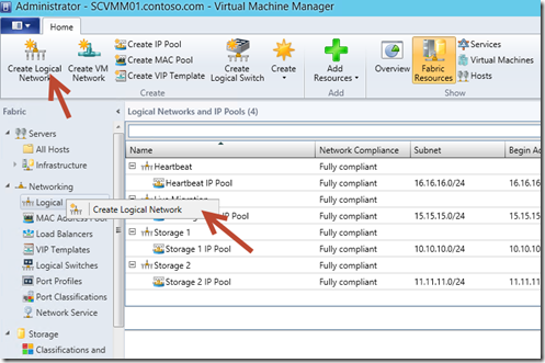
1. In SCVMM select the Fabric, expand Networking, and click Logical Networks. In the upper left hand corner of the ribbon navigation, click Create Logical Network. Or right-Click Logical Network and click Create Logical Network
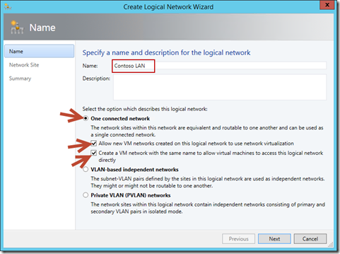
2. In the Create Logical Network Wizard window, in the Name page, type Contoso LAN in the Name
field. Ensure that the One connected network radio button is selected, check the boxes for Allow new
VM networks created on this logical network to use network virtualization and Create a VM
network with the same name to allow virtual machines to access this logical network directly,
and then click Next.
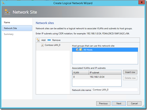
3. On the Network Site page, click Add . Contoso LAN_0 populates in the pane. Under Host groups that can use this network site select
All Hosts. Under Associated VLANs and IP subnets click Insert row, type the following settings, and then
click Next:
? VLAN: 0
? IP subnet: 192.168.1.0/24
On the Summary page, review the settings, and then click Finish.
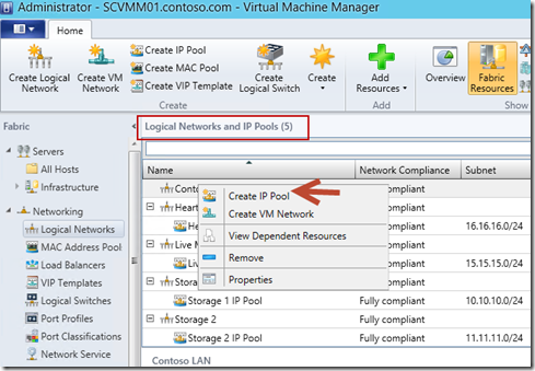
4. In the Logical Networks and IP Pools pane right-click Contoso LAN, and click Create IP Pool.
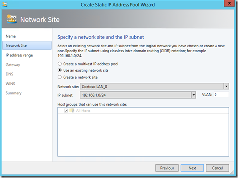
5. In the Create Static IP Address Pool Wizard, on the Name page, type Contoso LAN IP Pool in the Name field, ensure that the Logical Network selected is Contoso LAN, and then click Next. On the Network Site page, ensure that the Use an existing network site radio button is selected,
and then click Next.
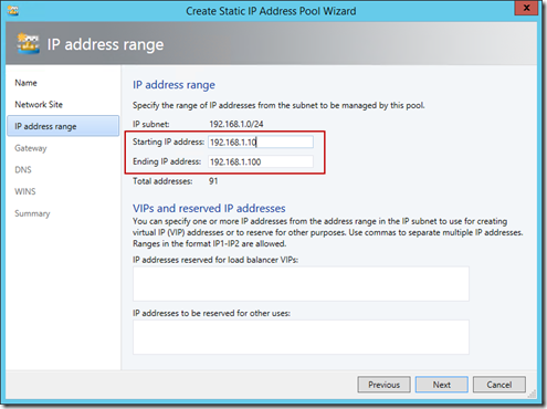
6. On the IP address range page, change the Starting IP address to 192.168.1.10 and the Ending IP
address to 192.168.1.100, and then click Next.
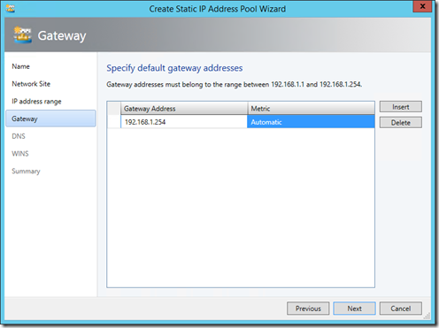
8. On the Gateway page, click Insert, enter 192.168.1.254, and then click Next.
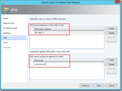
9. On the DNS page, next to DNS server addresses in the order of use, click Insert, and type 192.168.1.1 as the DNS Server address. Next to DNS search suffixes to append (in order), click Insert, and type contoso.com, and then click Next.
10. On the WINS page, leave the entry blank, and click Next. On the Summary page, click Finish.
Apply a Logical Network
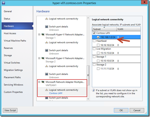
1. In SCVMM select the Fabric workspace, Expand Servers, and click All Hosts. In the main detail pane, right-click HYPER-V01, and select Properties.
2. Click the Hardware tab, scroll down to the NIC labeled VMTEAM1, and select Logical Network In the results pane, click the box for Contoso LAN.
3. Repeat the last steps with the following settings:
- Scroll to the NIC labeled Live Migration, select the Logical network connectivity tab, then select
the box for Live Migration. - Scroll to the NIC labeled Heartbeat, select the Logical network connectivity tab, then click the box
for Heartbeat. - Scroll to the NIC labeled Storage 1, select the Logical network connectivity tab, then click the box
for Storage 1. - Scroll to the NIC labeled Storage 2, select the Logical network connectivity tab, then click the box
for Storage 2.
4. Click OK in HYPER-V01 Properties.
5. Repeat steps 1 to 4 with Hyper-V02.
We have now created and applied our logical network to our environment. Next week, we will create port profiles and classifications that will be use with by logical switches, so that you can apply your port settings consistently to your network adapters and virtual network adapters. After we’ll configure port settings, configure logical switches and, as necessary, switch extensions (for Quality of Service (QoS), monitoring, or security).
We are that much closer to an Hyper-V cluster.
See you next week.
Cheers!
Pierre Roman | Technology Evangelist
Twitter | Facebook | LinkedIn
